


M440LX Server System Product Guide
161
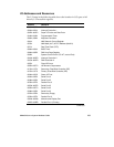
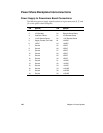
Interrupts
The following table shows the logical interrupt mapping of interrupt
sources on the system board.
Interrupt Description
(active-low signals have an “_L” symbol following them)
INTR Processor interrupt.
NMI NMI from DISMIC to processor.
IRQ0/MIRQ0 System board interrupt request 0 connected to input 2 of the I/O Apic. (For proper
operation, the BIOS must set the IRQ0 enable bit in PIIX3 register 70h during
initialization.)
IRQ1 RTC.
IRQ3 Serial port A or B interrupt from 87307VUL device, user configurable.
IRQ4 Serial port A or B interrupt from 87307VUL device, user configurable.
IRQ5 Parallel port.
IRQ6 Floppy diskette.
IRQ7 Parallel port.
IRQ8_L
IRQ9
IRQ10
IRQ11
IRQ12 Keyboard/mouse interrupt from 87307VUL.
IRQ14 Compatibility IDE interrupt from primary IDE devices 0 and 1.
IRQ15
IDE_IRQ Tide to IRQ14; hard wired from PIIX3.
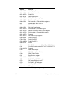
The following signals will be rerouted to the above interrupts:
PCI_INTA_L PCI Interrupt signal A from PIIX3. Wired to PCI-0 slot 1 INTA_L, PCI-0 slot 2 INTD_L,
PCI-0 slot 3 INTC_L, PCI-0 slot 4 INTB_L, PCI-1 slot 1 INTA_L, and PCI-1 slot 2
INTD_L.
PCI_INTB_L PCI Interrupt signal B from PIIX3. Wired to PCI-0 slot 1 INTB_L, PCI-0 slot 2 INTA_L,
PCI-0 slot 3 INTD_L, PCI-0 slot 4 INTC_L, PCI-1 slot 1 INTB_L, and PCI-1 slot 2
INTA_L. This interrupt is also used by the SCSI controller.
PCI_INTC_L PCI Interrupt signal C from PIIX3. Wired to PCI-0 slot 1 INTC_L, PCI-0 slot 2 INTB_L,
PCI-0 slot 3 INTA_L, PCI-0 slot 4 INTD_L, PCI-1 slot 1 INTC_L, and PCI-1 slot 2
INTB_L. This interrupt is also used by the Network controller.
PCI_INTD_L PCI Interrupt signal D from PIIX3. Wired to PCI-0 slot 1 INTD_L, PCI-0 slot 2 INTC_L,
PCI-0 slot 3 INTB_L, PCI-0 slot 4 INTA_L, PCI-1 slot 1 INTD_L, PCI-1 slot 2 INTC_L.
SMI_L System Management Interrupt. General-purpose error indicator from a control PAL that
provides an SMI_L from nontraditional error sources (PERR_L, SERR_L, and others).