


M440LX Server System Product Guide
165
Power System Control Signals
Power Enable/Disable (PON)
The PON control signal originates on the system board, and it is routed
through the power share backplane microcontroller. If the +5 V and +12 V
power going to the system board or the peripherals exceeds 240 VA, the
backplane microcontroller will disassert the PON control going to each
power supply (J4, J6, and J9). This signal is used to enable and disable the
power supplies.
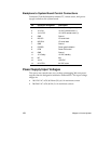
Remote Sense Connections
Individual remote sense outputs are provided to each +5 V and +3.3 V
power supply section. Remote voltage sense for +5 V and +3.3 V is done on
the system board. The +5 V and +3.3 V remote sense lines are routed
through the power share backplane and connect to the current sense
circuitry.
The +12 V is not sensed remotely. Instead, it is sensed on the power share
backplane.
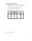
Load Share Connection
In systems with redundant power systems, the +5 V, +3.3 V, and +12 V
outputs from each power supply are routed through the power share
backplane. The current from each power supply output is monitored with a
current monitoring circuit. This current’s value is used to adjust the load
share of each power supply output.
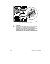
Output Power Connections
The +12 V, +5 V, and +3.3 V power outputs are routed through J1 to the
system board power connector. The +12 V and +5 V power outputs are also
routed through J5 to the peripheral power connector.
The -12 V, -5 V, and +5 V standby outputs are joined together through an
isolation circuit and connected to the system board through connector J1.