


14
Contents
Tables
1-1. Standard VGA Modes ............................................................................. 32
1-2. Extended VGA Modes............................................................................. 33
6-1. ECC Memory Banks................................................................................. 151
6-2. Sample DIMM Size Combinations.......................................................... 151
7-1. Total Combined Power Used by Your System ...................................... 174
7-2. Worksheet for Calculating DC Power Usage......................................... 175
8-1. System Board Jumpers............................................................................. 179
10-1. POST Beep Codes..................................................................................... 213
10-2. Port-80 Codes ........................................................................................... 214
10-3. POST Error Codes and Messages........................................................... 219
Figures
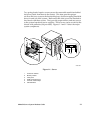
1-1. Server ........................................................................................................ 21
1-2. Back/Right Side View.............................................................................. 22
1-3. Controls and Indicators........................................................................... 24
1-4. Security Padlocks ..................................................................................... 26
2-1. Server I/O Panel ...................................................................................... 44
2-2. Power and Reset Buttons......................................................................... 46
4-1. Side Covers............................................................................................... 81
4-2. Top Cover................................................................................................. 83
4-3. Plastic Front Cover................................................................................... 85
4-4. Snap-in Plastic Peripheral Bay Cover..................................................... 86
4-5. Removing a Termination Board.............................................................. 89
4-6. Installing a Voltage Regulator Module................................................... 90
4-7. Installing a Pentium II Processor ............................................................ 91
4-8. Installing the Memory Module ............................................................... 93
4-9. Installing the RPX Module ...................................................................... 95
4-10. Expansion Slot Cover............................................................................... 98
4-11. Installing an ISA Add-in Board, Component-side Up.......................... 100
4-12. Installing a PCI Add-in Board, Component-side Down....................... 101
4-13. Removing the Diskette Drive.................................................................. 104
4-14. Diskette Drive and Carrier Assembly .................................................... 105
4-15. Filler Panels............................................................................................... 107
4-16. Removing the EMI Shield........................................................................ 108
4-17. Snap-in Plastic Slide Rails........................................................................ 109
4-18. Installing a 5.25-inch Peripheral Device................................................. 110
4-19. Lithium Back-up Battery ......................................................................... 114
4-20. Removing the Front Panel Board........................................................... 116