


166
Chapter 7 Power System
Power Good Circuit
The power good circuit looks at the levels of the power good (PGOOD)
signals. When the backplane PGOOD circuit senses a PGOOD signal, a
system PGOOD is asserted after an approximately 550 ms delay. Only a
single PGOOD signal assertion will cause the assertion of the system
PGOOD.
VA Monitor Circuit
The total supply current that forms part of the load sharing circuit monitors
+3.3 V as well as +5 V and +12 V on the system board. The microcontroller
determines the current supplied to the system board by subtracting the
peripheral current from the total current.
If either the system board power or peripheral power exceeds 240 VA, the
backplane microcontroller disables the supply outputs by disasserting PON.
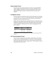
The following table shows the maximum available current to each of the
system connections. Resetting the circuit requires unplugging all of the
power supplies.
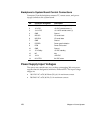
Connectors +5 V +12 V
J1 44 A (+4 A) 16 A (+4 A)
J5 44 A (+4 A) 16 A (+4 A)
The maximum current number shown is the sum of the currents from all
supplies.
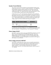
I²C Communication Circuit
The power share backplane microcontroller communicates with a similar
device on the system board through an I
2
C data link. This link reports the
number of power supplies in the server, current and power to the system
board and peripherals, and power supply status. The I
2
C signals are routed
through J2 to the system board.