


INSTALLATION
A-4 A-4
INVERTEC STT
Return to Section TOC Return to Section TOC Return to Section TOC Return to Section TOC
Return to Master TOC Return to Master TOC Return to Master TOC Return to Master TOC
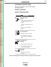
ELECTRIC SHOCK can kill.
• Only qualified personnel should
perform this installation.
•Turn the input power OFF at the
disconnect switch or fuse box
before installing this
equipment.
•Turn the power switch on the Invertec
STT “OFF” before connecting or discon-
necting input power lines, output cables,
or control cables.
• Do not touch electrically hot
parts.
• Always connect the ground terminal to a
good electrical earth ground.
WARNING
MACHINE GROUNDING AND HIGH
FREQUENCY INTERFERENCE
PROTECTION
The machine may not be suitable for use in an envi-
ronment where high frequency is present. For exam-
ple do not place the machine in close proximity to “TIG”
or “PLASMA” operations. To minimize high frequency
interference:
Locate the STT II power source more than 15
feet (4.5 m) away from high frequency units
and more than 25 feet (7.6 m) separation
between ground connections or welding arcs
of high frequency units.
Provide proper electrical ground to the
machine per local and national electrical
codes.
INPUT CONNECTIONS
FAILURE TO FOLLOW THESE INSTRUCTIONS
CAN CAUSE IMMEDIATE FAILURE OF COMPO-
NENTS WITHIN THE WELDER.
Turn the input power off at the disconnect switch
before attempting to connect the input power lines.
Connect the green lead of the power cord to ground
per local and national electrical codes.
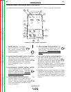
SUPPLY CONNECTIONS
Be sure the voltage, phase, and frequency of the input
supply is as specified on the rating plate. Input Power
supply line entry in provided on the case back of the
machine. See figure A.1 for location of the rating plate.
The Invertec STT II should be connected only by a
qualified electrician. Installation should be made in
accordance with local and national codes. Refer to the
“Technical Specifications” at the beginning of this
section for proper fuse sizes, ground wire, and input
supply power cable sizes.
Some models come from the factory with an input
power cord. If your model does not include the input
power cord install the proper size input cable and
ground cable according to “INPUT CABLE INSTAL-
LATION AND CONNECTION”.
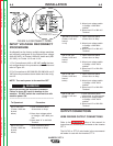
SELECT SUITABLE LOCATION
Locate the machine where there is free circulation of
clean air. Place the machine so that air can freely cir-
culate into the sides and out of the rear of the
machine. Dirt and dust that can be drawn into the
machine should be kept to a minimum. Failure to
observe these precautions can result in excessive
operating temperatures and nuisance shut down of the
Invertec STT II.
This machine carries an enclosure rating of IP21S. It
should not be placed in extremely damp or dirty loca-
tions. It should not be exposed to rain or snow.
STACKING
The Invertec STT II cannot be stacked.
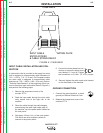
TILTING
Place the machine on a secure, level surface otherwise
the unit may topple over.
Read and understand entire Installation
Section before starting installation.