


Return to Section TOC Return to Section TOC Return to Section TOC Return to Section TOC
Return to Master TOC Return to Master TOC Return to Master TOC Return to Master TOC
TROUBLESHOOTING & REPAIR
F-69 F-69
INVERTEC STT
CAPACITOR REPLACEMENT
NOTE: Capacitors must always be replaced in
matched sets (C1 and C2 as a set).
When replacing Capacitors, remove the entire
FET heat sink assembly, including the capacitors
and switch board, as a unit.
Disassemble and reassemble only one unit at a
time. Use the other unit as a model during
reassembly so that all parts are reinstalled prop-
erly.
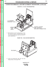
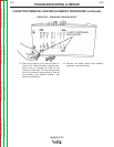
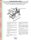
14. Remove the two 3/8” hex head nuts from the
top of the through-bolts. The hex nuts are
located on top of the fan shroud. See Figure
F.34.
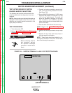
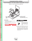
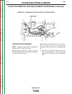
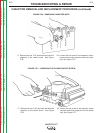
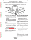
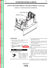
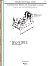
CAPACITOR REMOVAL AND REPLACEMENT PROCEDURE (continued)
FIGURE F.34 – REMOVING HEX HEAD NUTS OF THROUGH-BOLTS
HEX NUT