


Return to Section TOC Return to Section TOC Return to Section TOC Return to Section TOC
Return to Master TOC Return to Master TOC Return to Master TOC Return to Master TOC
TROUBLESHOOTING & REPAIR
F-74 F-74
INVERTEC STT
OUTPUT RECTIFIER REMOVAL AND REPLACEMENT (continued)
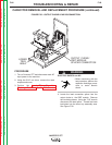
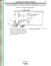
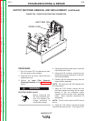
FIGURE F.39 – CHOKE LEAD/HEAT SINK CONNECTION
CHOKE LEAD
HEAT SINK TAB
PROCEDURE
1. Turn off Invertec STT and disconnect main
AC input power to the machine.
2. Using the 5/16" nut driver, remove the case
wraparound cover.
3.
Perform the Input Filter Capacitor
Discharge Procedure. See the Maintenance
section.
ELECTRIC SHOCK can kill.
• Before continuing with
the test procedure, per-
form the capacitor dis-
charge procedure to
avoid electric shock.
4. Using the slot head screw driver, loosen the
input cable strain relief.
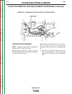
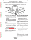
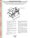
5. Using the 5/16" nut driver, remove the four
screws securing the case back to the inter-
nal horizontal baffles.
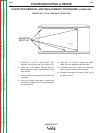
6. Carefully pull the case back away from the
output rectifier assembly.
NOTE: The case back will NOT detach from
the case bottom.
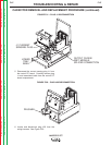
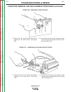
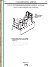
7. Using the 7/16" wrench, remove the four
bolts and washers mounting the fan motor
bracket to the top horizontal baffle.
Carefully set the fan and motor assembly
aside. Note insulation placement for
reassembly.
NOTE: The fan motor leads do NOT have to
be cut.
8. Using the 7/16" wrench, remove the choke
lead from the heat sink tab. See Figure F.39.
WARNING