


Return to Section TOC Return to Section TOC Return to Section TOC Return to Section TOC
Return to Master TOC Return to Master TOC Return to Master TOC Return to Master TOC
TROUBLESHOOTING & REPAIR
F-39 F-39
INVERTEC STT
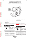
SNUBBER RESISTORS TEST (continued)
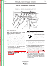
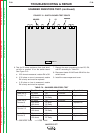
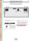
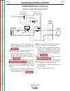
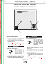
FIGURE F.13 - SWITCH BOARD TEST POINTS
6. Test for 25 ohms resistance from lead termi-
nal 401 to terminal 12 on the switch board.
See Figure F.13.
a. If 25 ohms is measured, resistor R4 is OK.
b. If 30 ohms or more is measured, resistor
R4 is faulty and must be replaced.
c. If 20 ohms or less is measured, resistor
R4 is faulty and must be replaced.
7. Repeat the same procedures to test R5, R6,
and R7 according to Table F.6.
8. Reconnect leads 401/403 and 402/404 to the
switch board.
9. Install the case wraparound cover.
L8441 L8441 SWITCHSWITCH
401401/403 1212
9
12402/404
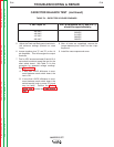
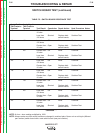
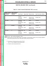
Check Test Result Conclusion Next Test Step Repair Action
Lead 401 to 25 ohms OK Continue
Terminal 12 >30 ohms R4 open Replace R4
<20 ohms R4 faulty
Lead 402 to 25 ohms OK Continue
Terminal 9 >30 ohms R5 open Replace R5
<20 ohms R5 faulty
Lead 403 to 25 ohms OK Continue
Terminal 12 >30 ohms R6 open Replace R6
<20 ohms R6 faulty
Lead 404 to 25 ohms OK Continue
Terminal 9 >30 ohms R7 open Replace R7
<20 ohms R7 faulty
> = GREATER THAN < = LESS THAN
TABLE F.6 – SNUBBER RESISTORS TEST