


Return to Section TOC Return to Section TOC Return to Section TOC Return to Section TOC
Return to Master TOC Return to Master TOC Return to Master TOC Return to Master TOC
TROUBLESHOOTING & REPAIR
F-62 F-62
INVERTEC STT
SWITCH BOARD REPLACEMENT (continued)
TEST AFTER REPAIR OF SWITCH
BOARDS AND/OR CAPACITORS
The following test must be performed after the
switch boards and/or the capacitors have been
replaced.
NOTE: Always make sure that switch boards are
changed in matched pairs. Never mix an old style
(different part number) switch board with a new
style (new part number).
TEST PROCEDURE
1. Turn main power OFF.
2. Perform Input Filter Capacitor Discharge
Procedure. See the Maintenance section.
ELECTRIC SHOCK can kill.
• Before continuing with the
test procedure, perform
the capacitor discharge
procedure to avoid electric
shock.
3. Connect a shorting conductor across termi-
nals 14 and 53 of the protection PC board.
See Figure F.29.
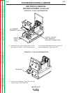
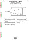
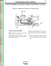
4. Set an ANALOG ohmmeter to X1000 range
and place the probes on terminals 9 (+) and
12 (–) of one switch board. The meter will
show the capacitors charging up and may
take a minute or so to stabilize. The final
meter reading should not exceed 8600 ohms
(8.6 on the scale).
5. Test the other switch board the same way.
NOTE: Repeat the Input Filter Capacitor
Discharge Procedure.
6. Remove the shorting conductor set up in step
3.
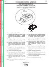
7. Replace 20 amp fuses with 5-amp fuses in
the input supply fuse holders.
NOTE: These fuses should be installed to pro-
tect against excessive current flow caused by a
short circuit during the procedure.
WARNING
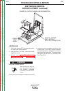
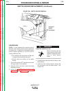
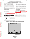
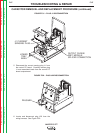
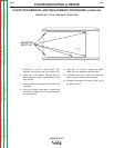
FIGURE F.29 — SHORTING TERMINALS 14 AND 53 OF PROTECTION BOARD
L7915-[ ]
PROTECTION
53
14
JUMPER TERMINALS