


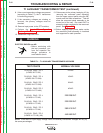

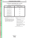
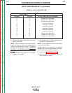

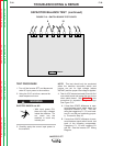

13. Check the secondary AC voltages accord-
ing to Table F.2.
14. With the correct 115VAC applied to the pri-
mary winding (#32 to #33), if any or all of
the secondary voltages are missing or low,
the T4 auxiliary transformer may be faulty.
Replace the T4 auxiliary transformer.
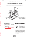
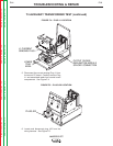
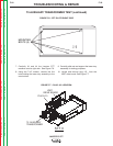
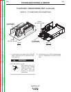
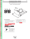
15. After all tests are completed, reconnect the
following:
Leads #32A, #32B, #33A, #33B to the
T4 transformer tabs
Plug J13 to the IGBT drive board
Plug J22 to the wiring harness
Reinstall lower tray assembly using
7/16” wrench and 5 bolts
Plug J1 to the control PC board
Reconnect lead splice from the output
choke to the IGBT module. Reposition
insulating sleeve.
16. Install the case wraparound cover.
TROUBLESHOOTING & REPAIR
F-24 F-24
INVERTEC STT
Return to Section TOC Return to Section TOC Return to Section TOC Return to Section TOC
Return to Master TOC Return to Master TOC Return to Master TOC Return to Master TOC
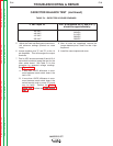
TABLE F.2 – T4 AUXILIARY TRANSFORMER VOLTAGES
TEST POINTS
PLUG J13 PINS 5 TO 6
PLUG J13 PINS 2 TO 3
PLUG J22 PINS 1 TO 2
(LEADS 240 TO 241)
PLUG J22 PINS 2 TO 9
(LEADS 241 TO 242)
PLUG J22 PINS 3 TO 4
(LEADS 243 TO 244)
PLUG J22 PINS 12 TO 13
(LEADS 245 TO 246)
NORMAL VOLTAGES
6VAC
10VAC
18VAC
18VAC
18VAC
18VAC
T4 AUXILIARY TRANSFORMER TEST (continued)