


Return to Section TOC Return to Section TOC Return to Section TOC Return to Section TOC
Return to Master TOC Return to Master TOC Return to Master TOC Return to Master TOC
TROUBLESHOOTING & REPAIR
F-14 F-14
INVERTEC STT
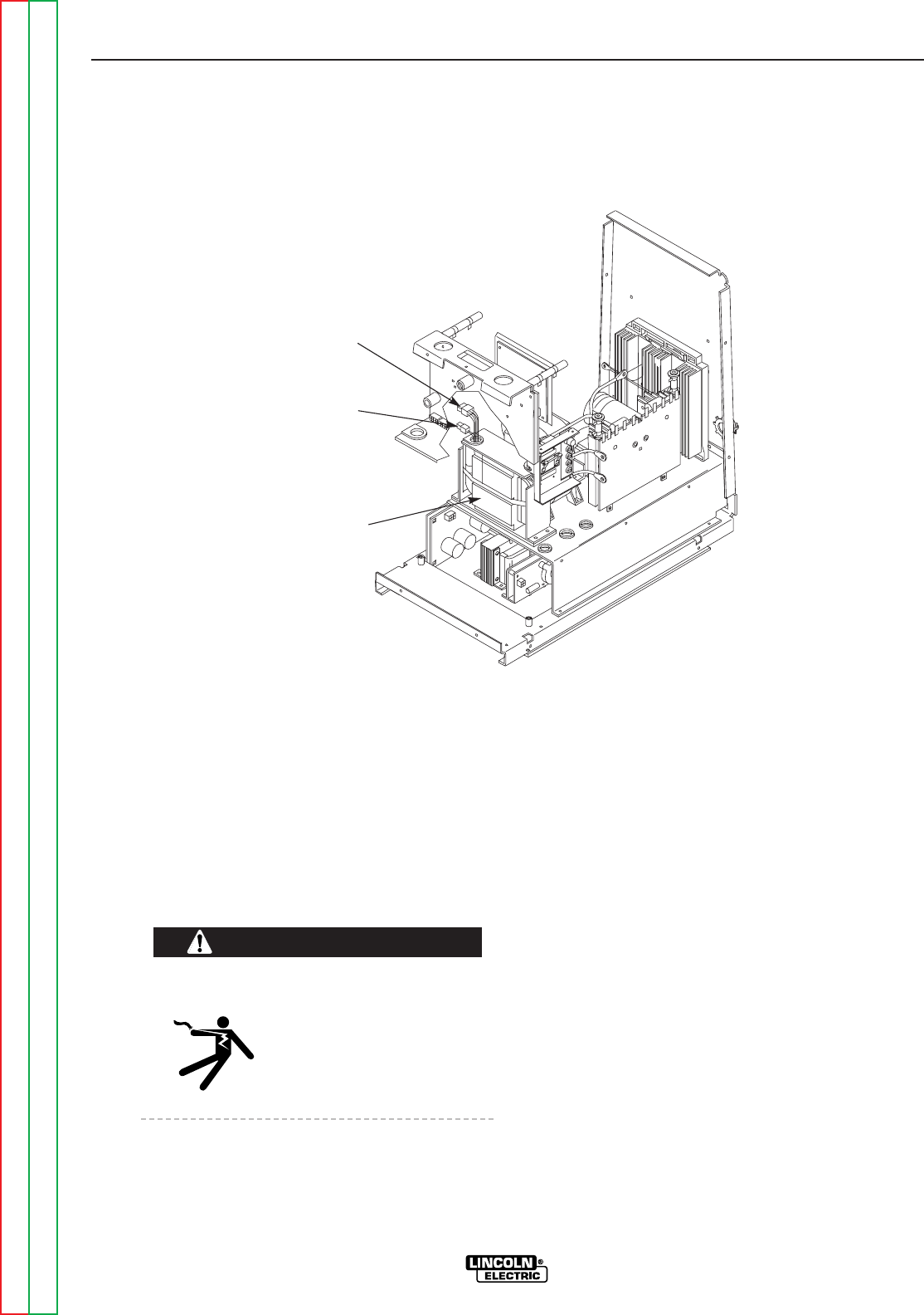
T1 AUXILIARY
TRANSFORMER
PLUG
J31
PLUG
J30
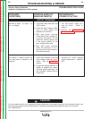
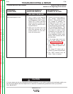
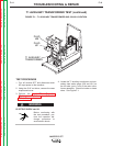
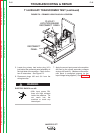
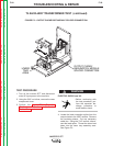
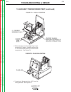
FIGURE F.1 – T1 AUXILIARY TRANSFORMER AND J30/J31 LOCATION
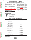
T1 AUXILIARY TRANSFORMER TEST (continued)
TEST PROCEDURE
1. Turn off Invertec STT and disconnect main
AC input power to the machine.
2. Using the 5/16" nut driver, remove the case
wraparound cover.
3. Perform the Input Filter Capacitor
Discharge Procedure. See the
Maintenance section.
ELECTRIC SHOCK can kill.
• Before continuing with
the test procedure, per-
form the capacitor dis-
charge procedure to
avoid electric shock.
4. Locate the T1 auxiliary transformer and sec-
ondary lead molex plugs (J30 and J31) on
the left side, just in front of the main trans-
former assembly. Check for broken or loose
wires. See Figure F.1.
WARNING