


OPERATION
B-6 B-6
INVERTEC STT
Return to Section TOC Return to Section TOC Return to Section TOC Return to Section TOC
Return to Master TOC Return to Master TOC Return to Master TOC Return to Master TOC
WELDING PARAMETERS AND GUIDE-
LINES
The Invertec STT II is neither a constant current (CC)
nor a constant voltage (CV) power source. In general,
wire diameter will be increased one size compared to
conventional (CV) power sources. The larger the wire
diameter the higher the deposition rate (Up to 1/16”).
Wire sizes below .035” are unnecessary for most appli-
cations. The Invertec STT II is a current controlled
machine which is capable of changing the electrode
current quickly in order to respond to the instantaneous
requirements of the arc and optimize performance.
By sensing changes in welding current, and hence the
electrode state, the power source will supply varying
output currents to minimize spatter. The Peak and
Background currents are two such current outputs that
can be adjusted.
Wire Feed Speed controls the deposition rate. Peak
Current controls the Arc Length. Background Current
controls the Bead Contour. And Tailout increases
Power in the Arc.
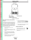
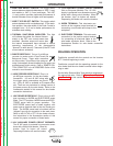
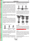
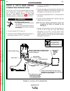
PEAK CURRENT
The Peak Current control acts similar to an “arc pinch”
control. Peak current serves to establish the arc length
and promote good fusion. Higher peak current levels
will cause the arc to broaden momentarily while
increasing the arc length. If set too high, globular type
transfer will occur. Setting this level to low will cause
instability and wire stubbing. In practice, this current
level should be adjusted for minimum spatter and pud-
dle agitation.
Adjust Arc Length
with Peak Current
Note: In 100% CO
2
shielding gas applications the peak
current level should be set greater than in a corre-
sponding application using a gas blend with a high per-
centage of Argon. Longer initial arc lengths with 100%
CO
2
are required to reduce spatter.
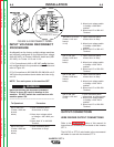
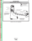
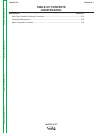
BACKGROUND CURRENT
The Background Current provides the control for the
overall heat input to the weld. Adjusting this level too
high will cause a large droplet to form and globular type
transfer to occur resulting in increased spatter.
Adjusting this level to low will cause wire stubbing and
also poor wetting of the weld metal. This is similar to a
low voltage setting on a standard CV machine
Adjust Bead Shape
using Background Current
Note: Background Current levels for applications using
100% CO2
is less than similar procedures involving gas
blends with high percentages of Argon. This is a result
of the greater heat generated in the 100% CO
2 arc.
(100% CO2 is 35 volts/cm and 100% Argon is 20
volts/cm. 75% Argon, 25% CO
2 is about 24 volts/cm.
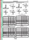
Contact
Tip to W
ork Distance
HOT START
The Hot Start control can be set to enhance establish-
ing the arc and provide the capability of increasing the
heat at the start of the weld to compensate for a cold
work piece. Hot start adjusts the time that additional
current is applied during the starting of the arc. Refer to
“Operational Features and Controls” in this section
for a description of this control.
TAILOUT
The tail out provides additional heat without the molten
droplet becoming too large. Increase as necessary to
add “Heat” to the arc without increasing arc length.
(This will allow for faster travel speeds and produce
improved wetting). As tailout is increased, the peal
and/or background current is usually reduced.
WELDING ARC PERFORMANCE
For optimum spatter reduction, the arc should be con-
centrated on the puddle.