


Return to Section TOC Return to Section TOC Return to Section TOC Return to Section TOC
Return to Master TOC Return to Master TOC Return to Master TOC Return to Master TOC
TROUBLESHOOTING & REPAIR
F-57 F-57
INVERTEC STT
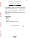
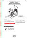
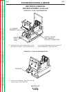
IGBT MODULE REMOVAL
AND REPLACEMENT (continued)
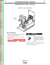
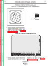
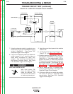
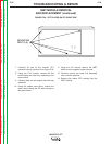
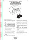
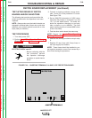
FIGURE F.27 – IGBT MODULE CONNECTIONS
E
E
IGBT
MODULE
C
G
STT II
For steps 14-18, see Figure F.27.
14. Using the phillips head screw driver, remove
the small leads from the small "E" and "B"
terminals. Note lead placement for reassem-
bly.
15. Using the 12mm wrench, remove the large
lead and the #289 lead from the large "E" ter-
minal. Note lead placement for reassembly.
16. Using the 12mm wrench, remove the large
lead and the #287 lead from the large "C"
terminal. Note lead placement for reassem-
bly.
17. Using the 3/16" Allen type wrench, remove
the four socket head cap screws that mount
the module to the heat sink.
18. Carefully remove the IGBT module.
19. Upon reassembly, use Dow Corning 340
Heat Sink Compound (Lincoln E1868)
between the module and the heat sink.
20. Mount the new module using the socket
head cap screws and torque to 35 inch
pounds.
Note: The torque should be rechecked after
three hours.
21. Using the 12mm wrench, assemble the large
lead and the smaller #289 lead to the large
"E" terminal. Torque to 86 inch pounds.
22. Using the 12mm wrench, assemble the large
lead and the smaller #287 lead to the large
"C" terminal. Torque to 86 inch pounds.
23. Using the phillips head screw driver,
reassemble the small leads to the small "E"
and "G" terminals. Torque to 13 inch
pounds.
24. Apply the Silicone Rubber RTV Coating
(Lincoln E2861 or Dow 3140) to the termi-
nals and lead connections as was previously
removed.
25. Replace the lower tray assembly.
26. Connect plug J22 to the wiring harness and
plug J1 to the control PC board.
27. Connect the lead splice between the output
choke and the IGBT module.
28. Install the case wraparound cover.