


Return to Section TOC Return to Section TOC Return to Section TOC Return to Section TOC
Return to Master TOC Return to Master TOC Return to Master TOC Return to Master TOC
TROUBLESHOOTING & REPAIR
F-16 F-16
INVERTEC STT
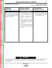
8. If the correct secondary voltages are present
(according to Table F.1), the T1 transformer
is functioning properly.
9. If the secondary voltages are missing or
incorrect, the primary voltages must be
checked.
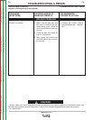
10. Remove input power to the STT machine.
11. Perform the Input Filter Capacitor
Discharge Procedure.
12. Reconnect Plugs J30 & J31.
ELECTRIC SHOCK can kill.
• Before continuing with
the test procedure, per-
form the capacitor dis-
charge procedure to
avoid electric shock.
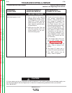
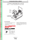
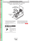
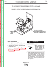
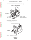
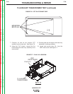
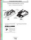
13. Gain access to the primary lead plug J21 by
removing the reconnect panel assembly
from the upper support panel using the 3/8"
wrench and slot head screwdriver. This will
allow the reconnect panel assembly to be
moved out of the way. Be careful NOT to
stress the leads connected to the reconnect
panel. See Figure F.2.
14. Before applying input power make certain
the reconnect panel assembly is insulated
and supported for safe operation.
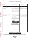
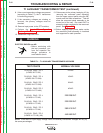
T1 AUXILIARY TRANSFORMER TEST (continued)
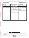
TABLE F.1 – T1 AUXILIARY TRANSFORMER VOLTAGES
TEST POINTS
PLUG J30 PINS 1 TO 2
(LEADS 32 TO 33)
PLUG J31 PINS 1 TO 4
(LEADS 501 TO 504)
PLUG J31 PINS 2 TO 3
(LEADS 212 TO 503)
PLUG J31 PINS 2 TO 5
(LEADS 212 TO 43A)
PLUG J21 PINS 1 TO 4
(LEADS H1 TO H2)
PLUG J21 PINS 1 TO 2
(LEADS H1 TO H3)
PLUG J21 PINS 1 TO 3
(LEADS H1 TO H4)
PLUG J21 PINS 1 TO 6
(LEADS H1 TO H5) (H6)
NORMAL VOLTAGE
115VAC
18VAC
24VAC
42VAC
200/208VAC
220/230VAC
380/415VAC
440/460VAC
WARNING
NOTE: If the main AC input supply voltage varies, the auxiliary transformer voltages will vary by
the same percentages.