


Return to Section TOC Return to Section TOC Return to Section TOC Return to Section TOC
Return to Master TOC Return to Master TOC Return to Master TOC Return to Master TOC
TROUBLESHOOTING & REPAIR
F-43 F-43
INVERTEC STT
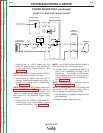
POWER BOARD TEST (continued)
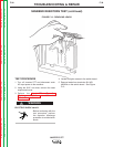
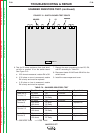
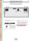
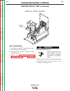
FIGURE F.15 – POWER PC BOARD TEST POINTS
POWER BOARD
J6
J7
J14
L8033
501
504
302
275
211A
305
311
313
309
310
301
212A
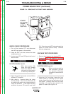
4. Secure and insulate the front panel assembly
for POWER ON testing.
ELECTRIC SHOCK can kill.
• With input power ON,
there are high voltages
inside the machine. Do
not reach into the machine
or touch any internal part.
5. Apply the correct input power and turn ON the
machine.
6. Carefully test for 18VAC input from the T1
Auxiliary Transformer between plug J7 pin 5
(lead#501) and plug J7 pin 6 (lead #504) at
the power PC board. See Figure F. 15.
NOTE: If the 18VAC is NOT present, perform
the T1 Auxiliary Transformer Test. Also check
associated wiring. See the Wiring Diagram.
WARNING