


Return to Section TOC Return to Section TOC Return to Section TOC Return to Section TOC
Return to Master TOC Return to Master TOC Return to Master TOC Return to Master TOC
TROUBLESHOOTING & REPAIR
F-47 F-47
INVERTEC STT
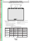
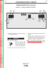
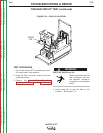
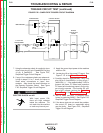
FIGURE F.18 - LEADS #309, #309A AT CR1, CR2 RELAYS
CR2
CR1
309A
309
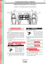
PROTECTION BOARD TEST (continued)
7. If the Capacitor Balance Test is OK and
more than 5VDC is present at leads #311 to
#313 (Step 6), the protection PC board may
be faulty.
NOTE: The above voltage checks pertain only
to the over voltage signal from the protection
PC board to the power PC board. The capaci-
tor precharge circuits are also incorporated
within the protection PC board. If the problem
has not been identified, carefully proceed with
the following steps.
8. Remove input power to the Invertec STT
machine.
9.
Perform the Input Filter Capacitor Discharge
Procedure. See the Maintenance section.
ELECTRIC SHOCK can kill.
• Before continuing with
the test procedure, per-
form the capacitor dis-
charge procedure to
avoid electric shock.
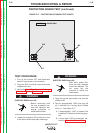
10. Locate and remove leads #309 and #309A
from CR1 and CR2 relays. See Figure
F.18.
ELECTRIC SHOCK can kill.
•
With input power ON,
there are high voltages
inside the machine. Do
not reach into the machine
or touch any internal part.
11. Apply correct input power and turn ON the
machine.
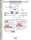
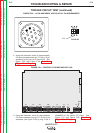
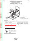
12. Check for approximately 12VDC from plug
J15 pin 1 (lead #314)(+) to plug J15 pin 4
(lead#315) (-). See Figure F.17.
13. Check for approximately 12VDC from plug
J15 pin 3 (lead #316)(+) to plug J15 pin 6
(lead#317) (-). See Figure F.17.
14. If a low voltage is present in either steps 12
or 13 (approximately 1VDC), perform the
Capacitor Balance Test.
15. If the Capacitor Balance Test is OK, the
protection PC board may be faulty.
16. Be certain to replace leads #309 and #309A
onto the CR1 and CR2 relays.
17. After all tests are completed, install the
case wraparound cover.
WARNING
WARNING