


Return to Section TOC Return to Section TOC Return to Section TOC Return to Section TOC
Return to Master TOC Return to Master TOC Return to Master TOC Return to Master TOC
TROUBLESHOOTING & REPAIR
F-46 F-46
INVERTEC STT
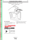
PROTECTION BOARD TEST (continued)
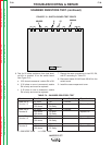
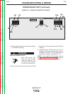
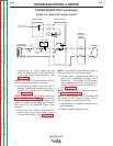
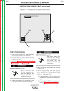
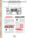
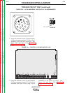
FIGURE F.17 – PROTECTION PC BOARD TEST POINTS
PROTECTION
L7915-[ ]
313
311
J8
J15
315
317
314
316
TEST PROCEDURE
1. Turn off the Invertec STT and disconnect
main AC input power to the machine.
2. Using the 5/16" nut driver, remove the case
wraparound cover.
3.
Perform the Input Filter Capacitor Discharge
Procedure. See the Maintenance section.
ELECTRIC SHOCK can kill.
• Before continuing with
the test procedure, per-
form the capacitor dis-
charge procedure to
avoid electric shock.
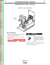
4. Locate the protection PC board just in front
of the input rectifier and relay mountings.
ELECTRIC SHOCK can kill.
• With input power ON,
there are high voltages
inside the machine. Do
not reach into the
machine or touch any
internal part.
5. Apply the correct input power and turn the
machine ON.
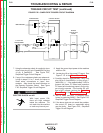
6. Test for approximately 1VDC from plug J8
pin 1 (lead #311)(+) to plug J8 pin 3 (lead
#313) (-). See Figure F.17.
A. If approximately 1VDC is present, the
protection PC board is functioning prop-
erly.
B. If more than 5 VDC is measured, per-
form the Capacitor Balance Test.
WARNING
WARNING