


MAINTENANCE
D-2 D-2
INVERTEC STT
Return to Section TOC Return to Section TOC Return to Section TOC Return to Section TOC
Return to Master TOC Return to Master TOC Return to Master TOC Return to Master TOC
WARNING
Failure to follow this
capacitor discharge proce-
dure can result in electric
shock.
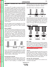
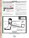
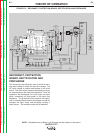
INPUT FILTER CAPACITOR
DISCHARGE PROCEDURE
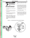
1. Turn off input power or disconnect input
power lines.
2. Remove hex head screws from side and
top of machine and remove wrap-around
machine cover.
3. Be careful not to make contact with the
capacitor terminals that are located in the
center of the Switch Boards.
4. Obtain a high resistance and high
wattage resistor (25-1000 ohms and 25
watts minimum). This resistor is not sup-
plied with machine. NEVER USE A
SHORTING STRAP FOR THIS PROCE-
DURE.
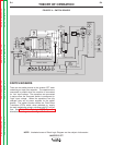
5. Locate the two capacitor terminals (large
hex head cap screws) shown in Figure
D.1.
6. Use safety glasses, electrically insulated
gloves and insulated pliers. Hold body of
the resistor and connect resistor leads
across the two capacitor terminals. Hold
resistor in place for 10 seconds. DO NOT
TOUCH CAPACITOR TERMINALS WITH
YOUR BARE HANDS.
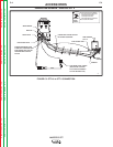
7. Repeat discharge procedure for capaci-
tor on other side of machine.
8. Check voltage across terminals of all
capacitors with a DC voltmeter. Polarity
of capacitor terminals is marked on PC
board above terminals. Voltage should be
zero. If any voltage remains, repeat this
capacitor discharge procedure.
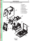
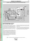
FIGURE D.1 — LOCATION OF INPUT FILTER CAPACITOR TERMINALS.