


Return to Section TOC Return to Section TOC Return to Section TOC Return to Section TOC
Return to Master TOC Return to Master TOC Return to Master TOC Return to Master TOC
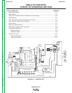
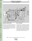
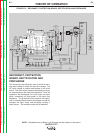
THEORY OF OPERATION
E-5 E-5
INVERTEC STT
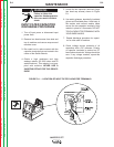
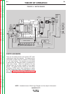
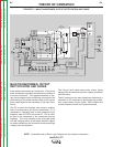
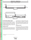
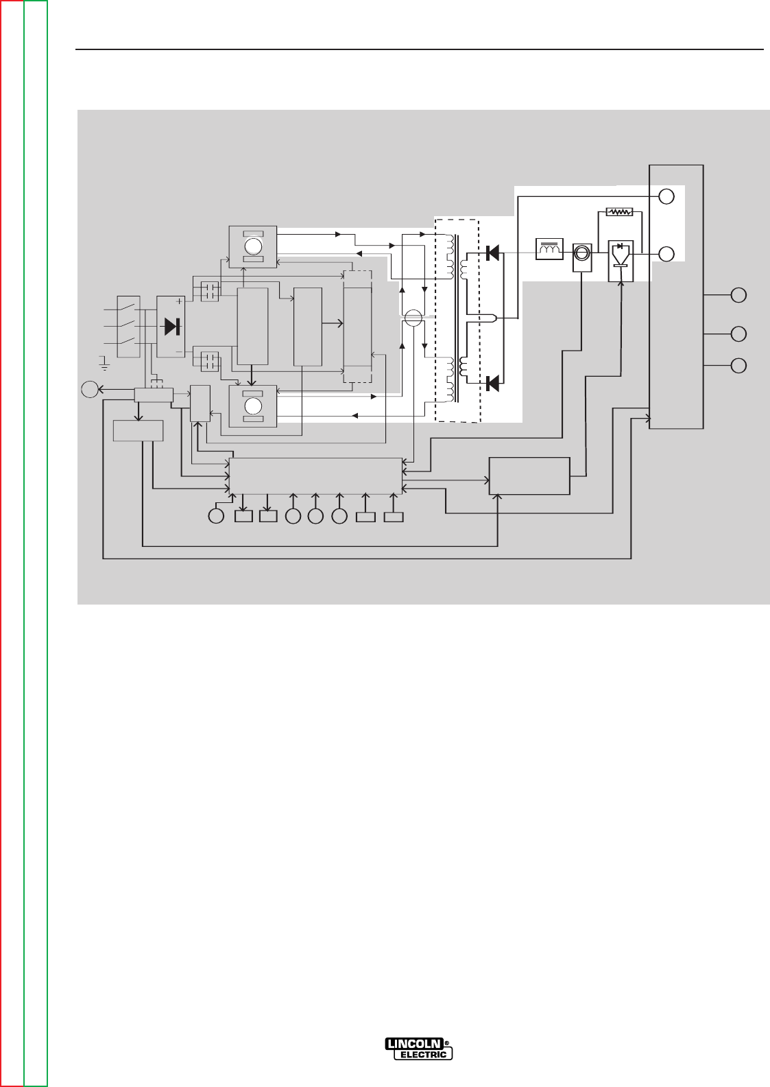
FIGURE E.5 – MAIN TRANSFORMER, OUTPUT RECTIFICATION AND CHOKE
MAIN TRANSFORMER, OUTPUT
RECTIFICATION AND CHOKE
Each switch board works as a switch pair. Each board
feeds a separate, oppositely wound primary winding of
the main transformer. The opposite directions of cur-
rent flow through the main transformer primary and the
offset timing of the switch boards induce an AC square
wave output signal at the secondary of the main trans-
former.
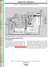
The DC current flow through each primary winding,
which is monitored by the current transformer T3, is
redirected or "clamped" back to each respective input
capacitor when the FETs are turned off. This is need-
ed due to the inductance of the transformer primary
windings. The cross coupling of the primaries along
with the clamping action of the diode maintain capaci-
tor balance when they are connected in the series (high
voltage) input configuration.
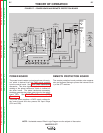
The firing of both switch board pairs occurs during
halves of 50 microsecond intervals, creating a constant
20 KHZ output.
The AC output from the main transformer secondary is
rectified to a DC output and is applied through a stabi-
lizer output choke, current sensor, IGBT module and
remote protection board to the output terminals.
NOTE: Unshaded areas of Block Logic Diagram are the subject of discussion.
POSITIVE
OUTPUT
TERMINAL
TERMINAL
OUTPUT
NEGATIVE
CONTROL BOARD
IGBT
DRIVER
BOARD
P
O
W
E
R
B
O
A
R
D
FAN
TRANS
T1
TRANS
T4
S
W
I
T
C
H
B
O
A
R
D
S
W
I
T
C
H
B
O
A
R
D
R
E
C
O
N
N
E
C
T
P
R
O
T
E
C
T
I
O
N
INPUT
RECTIFIER
LINE
SWITCH
CR1
CR2
B
O
A
R
D
D
R
I
V
E
R
B
O
A
R
D
PRE -
CHARGE
PRE -
CHARGE
CHOKE
CURRENT
SENSOR
IGBT
MODULE
1 OHM
PEAK
CURRENT
METER
BACK-
METER
PEAK
CURRENT
CONTROL
BACK-
CONTROL
HOT
START
CONTROL
WIRE
SIZE
SWITCH
WIRE
TYPE
SWITCH
VOLTAGE
SENSING
RECEPTACLE
REMOTE
CONTROL
RECEPTACLE
WIRE
RECEPTACL
E
FEEDER
R
E
M
O
T
E
P
R
O
T
E
C
T
I
O
N
B
O
A
R
D
CURRENT
TRANS
T3
MAIN
TRANSFORMER
T2
115
VAC
18
VAC
2
4
V
A
C
"A"
LEAD
15VDC
T
H
E
R
M
O
S
T
A
T
CURRENT FEEDBACK
42VAC
VOLTAGE FEEDBACK
10VAC AND 6VAC
D
R
I
V
E
S
I
G
N
A
L
36VAC
GUN TRIGGER
LESS THAN 1VDC
PWM SIGNAL
PULSE TRANSFORMER SIGNAL
GROUND
GROUND
FET
FET
FET
FET
CAP
CAP
TAILOUT
CONTROL
(STT II ONLY)