


Return to Section TOC Return to Section TOC Return to Section TOC Return to Section TOC
Return to Master TOC Return to Master TOC Return to Master TOC Return to Master TOC
TROUBLESHOOTING & REPAIR
F-34 F-34
INVERTEC STT
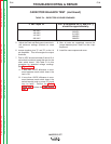
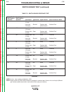
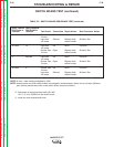
SWITCH BOARD TEST (continued)
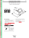
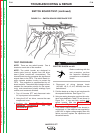
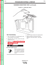
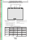
FIGURE F.11 - SWITCH BOARD RESISTANCE TEST
TEST PROCEDURE
NOTE: There are two switch boards. One is
located on each side of the machine.
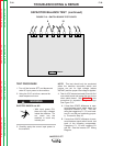
NOTE: The switch boards are designed to
receive gate (turn-on) signals from the driver
board (pulse transformer secondaries). The
internal board circuitry processes the signals and
outputs them to the FETs. The switch board cir-
cuitry contains snubber circuitry to protect the
FETs. This protection is supplemented by off-
board resistors. The switch board design accom-
modates the connection point(s) for the capaci-
tor(s), main transformer primary windings, input
rectifier, and reconnect switches.
1. Turn off Invertec STT and disconnect main
AC input power to the machine.
2. Using the 5/16" nut driver, remove the case
wraparound cover.
3. Perform the Input Filter Capacitor
Discharge Procedure. See the
Maintenance section.
ELECTRIC SHOCK can kill.
• Before continuing with the
test procedure, perform
the capacitor discharge
procedure to avoid electric
shock.
4. Disconnect all wiring harness leads
(401/403, 1/8, 9, 12, 4/5, 402/404) from the
switch board.
5. Fold the leads up so they do not interfere with
the exposed terminals. See Figure F.11.
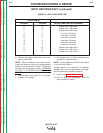
6. Using an analog ohmmeter, perform the resis-
tance tests detailed in Table F.5 and shown in
Figure F.11. If any test fails, replace both
switch boards. See the Switch Board
Removal and Replacement procedure.
7. If the switch boards appear to be burned or
overheated, or if the machine was supplied by
a 380 VAC or higher voltage supply when the
failure occurred, replace the capacitors and
the switch boards.
WARNING