


Return to Section TOC Return to Section TOC Return to Section TOC Return to Section TOC
Return to Master TOC Return to Master TOC Return to Master TOC Return to Master TOC
TROUBLESHOOTING & REPAIR
F-42 F-42
INVERTEC STT
POWER BOARD TEST (continued)
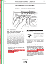
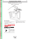
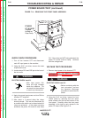
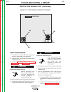
FIGURE F.14 – REMOVING THE FRONT PANEL ASSEMBLY
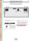
POWER
PC BOARD
(Located
on Back of
Case Front)
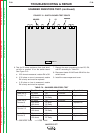
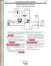
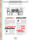
QUICK CHECK PROCEDURE
1. Turn off the Invertec STT and disconnect
main AC input power to the machine.
2. Using the 5/16" nut driver, remove the case
wraparound cover.
3. Locate relays CR1 and CR2 just to the front of
the fan motor.
ELECTRIC SHOCK can kill.
• With input power ON,
there are high voltages
inside the machine. Do
not reach into the machine
or touch any internal part.
4. Apply the correct input power and turn ON the
Invertec STT machine.
5. After about a 5 second delay the relays
should activate. This can be determined by
an audible click which can be heard when the
relays are activated. If the relays are being
activated, the power PC board is most likely
OK. If the relays are NOT being activated, the
power PC board could be faulty. Continue
with the voltage tests.
VOLTAGE TEST PROCEDURE
1. Remove input power to the Invertec STT.
2.
Perform the Input Filter Capacitor Discharge
Procedure. See the Maintenance section.
ELECTRIC SHOCK can kill.
• Before continuing with the
test procedure, perform
the capacitor discharge
procedure to avoid electric
shock.
3. Using the 5/16" nut driver, loosen the front
control panel by removing the four sheet
metal screws from the top and bottom of the
front panel. Carefully move the front panel
assembly to the right to gain access to the
power PC board. See Figure F.14.
WARNING
WARNING