


ACCESSORIES
C-2 C-2
INVERTEC STT
Return to Section TOC Return to Section TOC Return to Section TOC Return to Section TOC
Return to Master TOC Return to Master TOC Return to Master TOC Return to Master TOC
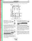
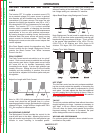
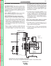
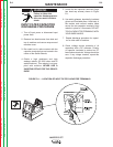
STT control board to accept PEAK and BACK-
GROUND inputs on this connector rather than from
the front panel controls. If this short is removed, the
front panel controls will be active. By adding a switch
between pins “J” and “B” a “LOCAL/REMOTE” con-
trol switch can be created. (Switch open for “local”
and closed for “remote”)
3. For robotic control of the PEAK CURRENT, a 0 to
+10 volt DC signal is applied between pins “A” and
“G” with + applied to pin “G”. The BACKGROUND
CURRENT is controlled with a similar signal applied
between pins “A” and “C” with + applied to pin “C”.
In this application pins “J” and “B” must be shorted
as described in 2 above.
NOTE: These analog signals should be isolated
from the robot circuitry to prevent interference.
4. The trigger switch is connected between pins “D”
and “F”. These connections are in parallel with the
trigger switch from the wire feeder.
5. The digital meters for PEAK and BACKGROUND
currents will show preset values in both local and
remote operation.
OPTIONS / ACCESSORIES
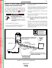
K940 SENSE LEADS: These leads are used to accu-
rately sense arc voltage. One set is required for each
STT II power source. A 10 ft and 25 ft set are provid-
ed as standard with the machine. Additional sets are
available in 10 ft (K940-10), 25 ft (K940-25) and 50 ft
(K940-50) lengths.
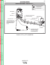
K942-1 REMOTE CONTROL: Allows remote adjust-
ment of Peak and Background Current settings.
REMOTE RECEPTACLE (For optional remote interface,
Connection to the STT-10 Wire Feeder or Robotic Control)
1. The 10 pin MS connector labeled “Remote Control”
located on the front panel of the STT is used for
remote control of the power source. Control for the
PEAK (PB pot) and BACKGROUND (BG pot) cur-
rent along with the trigger switch is provide through
this connector.
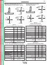
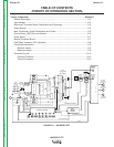
2. Refer to figure C.1 below for details about the
remote receptacle (J38). Note that pins “J” and “B”
are shorted together This “short circuit” tells the
+ ARC
- ARC
1
2
3
4
VOLTAGE
SENSE
CONNECTION
J19
290
291
(+)
(-)
J
B
C
G
A
D
F
H
E
I
TRIGGER
GND
BG
PB
10K
10K
OPTIONAL
REMOTE
INTERFACE
223
7
J38
33C
1
2
3
4
J37
8
6
1
5
8
4
3
2
212C
43A
212B
32C
3
1
2
10
9
12
4
11
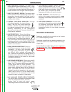
J38
REMOTE
PROTECTION BOARD
PORTION OF G3136 WIRING DIAGRAM
REFER TO ACTUAL DIAGRAM PASTED INSIDE YOUR MACHINE
N
ELECTRODE SENSE LEAD
290A
J39
WIRE
FEEDER