


Return to Section TOC Return to Section TOC Return to Section TOC Return to Section TOC
Return to Master TOC Return to Master TOC Return to Master TOC Return to Master TOC
TROUBLESHOOTING & REPAIR
F-56 F-56
INVERTEC STT
IGBT MODULE REMOVAL
AND REPLACEMENT (continued)
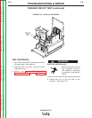
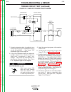
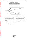
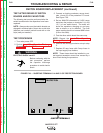
FIGURE F.26 – STT PLACED ON ITS RIGHT SIDE
MOUNTING
BOLTS (5)
7. Carefully lift and tilt the Invertec STT
machine onto its right side. See Figure F.26.
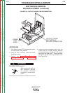
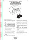
8. Using the 7/16" wrench, remove the five
bolts holding the lower tray assembly to the
case bottom.
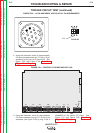
9. Carefully slide out and support the lower tray
assembly.
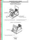
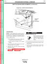
10. Using the needle nose pliers, remove the
strain relief holding the J22 lead harness to
the case bottom.
11. Using the 1/2" wrench, remove the IGBT
cable from the negative output terminal.
12. Carefully remove the lower tray assembly
clear from the machine.
13. Remove the rubber RTV coating from the
IGBT module.