


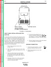
INSTALLATION
A-5 A-5
INVERTEC STT
Return to Section TOC Return to Section TOC Return to Section TOC Return to Section TOC
Return to Master TOC Return to Master TOC Return to Master TOC Return to Master TOC
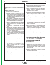
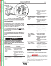
INPUT CABLE INSTALLATION AND CON-
NECTION
A cable strain relief is provided at the supply line entry
and is designed to accommodate cable diameters of
.310 - 1.070 in. (7.9 - 27.2 mm). On European models
the strain relief is designed to accommodate cable
diameters of .709 - 1.000 in. (18.0 - 25.4 mm). Refer to
“Technical Specifications” at the beginning of this sec-
tion for the proper input cable sizes. Refer to Figure A.1
and perform the following steps:
1. Remove the wraparound cover of the
Invertec STT II.
2. Feed the input cable through the input cable
entry access hole at the right rear of the
machine.
3. Route the cable through the cable hangers,
located along the lower right inside edge of
the machine, up to the power switch located on
the front panel.
4. Strip away 102 mm (4 in.) of the outer jacket.
Trim fillers and strip conductor jackets to
connect to the power switch.
5. Connect the three phase line con-
ductors to the power switch termi-
nals labeled U, V and W. Tighten
the connections to 3.0 Nm. (27 in.-lb.) torque.
6. Securely tighten the cable strain relief located
on the case back of the machine.
GROUND CONNECTION
1. Connect the ground terminal to earth
ground per National Electrical Code.
2. Replace the wraparound cover of the
Invertec STT II.
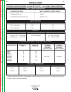
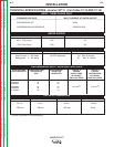
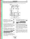
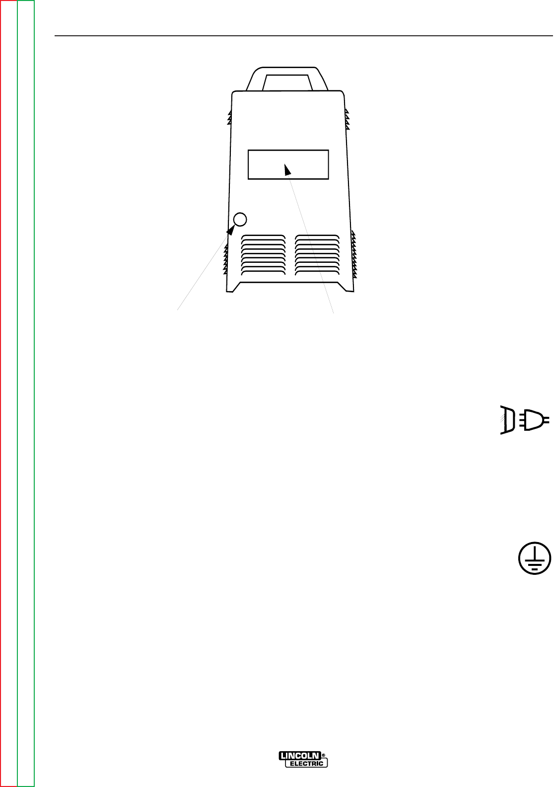
CASE BACK
RATING PLATE
INPUT CABLE
ENTRY ACCESS
& CABLE STRAIN RELIEF
FIGURE A.1 CASE BACK