


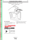

5. Adjust the Peak and Background controls to
the minimum settings (controls on case
front).
6. Jumper together pins "C" and "D" on the 14
pin amphenol. This will energize the output
terminals.
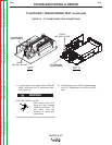
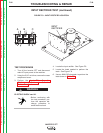
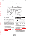
7. Test for VDC across terminals #9 and #12 of
one switch board and repeat the test for the
other switch board. See Table F.4 in this
procedure for expected voltage readings.
See Figure F.10.
A. If less than 15VDC difference is mea-
sured between each switch board, the
test is OK.
B. If more than 15VDC difference is mea-
sured between each switch board, the
switch board(s) and or power PC board
may be faulty. Perform the Switch
Board Test. Perform the Power Board
Test.
8. After all tests are completed, remove the
jumper between pins C and D on the 14-pin
amphenol.
9. Install the case wraparound cover.
TROUBLESHOOTING & REPAIR
F-31 F-31
INVERTEC STT
Return to Section TOC Return to Section TOC Return to Section TOC Return to Section TOC
Return to Master TOC Return to Master TOC Return to Master TOC Return to Master TOC
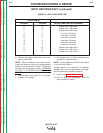
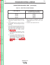
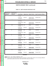
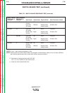
CAPACITOR BALANCE TEST (continued)
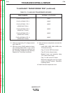
TABLE F.4 – EXPECTED VOLTAGE READINGS
If VAC Input is:
460 VAC
440 VAC
415 VAC
380 VAC
VDC at terminals #9 (+) and #12 (-)
should be approximately:
325VDC
311VDC
293VDC
269VDC