


Return to Section TOC Return to Section TOC Return to Section TOC Return to Section TOC
Return to Master TOC Return to Master TOC Return to Master TOC Return to Master TOC
TROUBLESHOOTING & REPAIR
F-60 F-60
INVERTEC STT
SWITCH BOARD REPLACEMENT (continued)
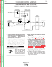
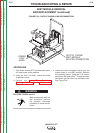
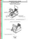
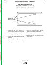
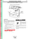
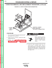
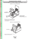
FIGURE F.28 – SWITCH BOARD REMOVAL
PROCEDURE
NOTE: If a test indicates that a switch board is
defective, both switch boards must be replaced at
the same time. In addition to replacing the switch
boards, replace capacitors C1 and C2 if the fol-
lowing conditions exist:
a. The machine was operating from 380 VAC
or higher when the failure occurred.
b. Burned areas are visible on the switch
boards.
1. Turn off the Invertec STT and disconnect main
AC input power to the machine.
2. Using the 5/16" nut driver, remove the case
wraparound cover.
3.
Perform the Input Filter Capacitor Discharge
Procedure. See the Maintenance section.
ELECTRIC SHOCK can kill.
• Before continuing with the
test procedure, perform the
capacitor discharge proce-
dure to avoid electric
shock.
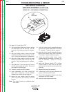
4. Carefully disconnect the leads at the top of the
switch board.
5. Using the 3/16" socket wrench, remove the
four cap screws from the switch board. See
Figure F.28.
WARNING
SOCKET
HEAD
SCREWS