


A-6
INSTALLATION
A-6
INVERTEC STT II
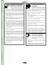
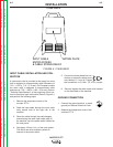
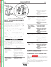
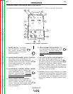
FIGURE A.2 RECONNECT PANEL
I
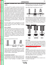
NPUT VOLTAGE RECONNECT
PROCEDURE
As shipped from the factory, multiple voltage machines
are internally configured for the highest input voltage
(440-460 VAC), for Codes 11092 and below and (380-
415 VAC), for Codes 11115 and 11116.
1. For Connections to 440 or 460 VAC verify
the inter-
nal configurations to the procedures shown below and
refer to Figure A.2.
2. For Connections to 200,208,220,230,380,400 or 415
VAC follow the procedure shown below and refer to fig-
ure A.2.
NOTE: Turn main power to the machine OFF
before performing the reconnect procedure.
Failure to do so will result in damage to the
machine. DO NOT switch the reconnect bar with
machine power ON.
------------------------------------------------------------------------
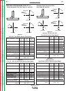
To Operate at Procedure
460 or 440 VAC 1. Open reconnect panel
(Codes 11092 and access door on wrap-
around.
below) 2. Move input voltage switch
to Voltage = 380 -460V pos-
ition.
3. Move lead “A” to 440-460
Terminal.
380 or 415 VAC 1. Open reconnect panel
(Codes 11092 and access door on wrap-
around.
below)
2. Move input voltage switch
to Voltage = 380-460V
position.
3. Move lead “A” to 380-415
Terminal.
380,400 or 415 VAC 1. Open reconnect panel
(Codes 11115 and access door on wrap-
around.
11116) 2. Move input voltage switch
to Voltage = 380-460V
position.
3. Move lead “A” to 380-415
Terminal.
220 or 230 VAC 1. Open reconnect panel
(Codes 11092 and access door on wrap-
around.
below) 2. Move input voltage switch
to Voltage = 200 -230V
position.
3. Move lead “A” to 220-230
Terminal.
200 or 208 VAC 1. Open reconnect panel
(Codes 11092 and access door on wrap-
around.
below) 2. Move input voltage switch
to Voltage = 200 -230V
position.
3. Move lead “A” to 200-208
Terminal.
200 or 208 VAC 1. Open reconnect panel
(Codes 11115 and access door on wrap-around.
11116) 2. Move input voltage switch
to Voltage = 200 -230V
position.
3. Move lead “A” to 200-208
Terminal.
OUTPUT CONNECTIONS
WIRE FEEDER OUTPUT CONNECTIONS
Refer to the Accessories section of this manual for
instructions on connecting a wire feeder to the Invertec
STT II.
The LN-742 or STT-10 wire feeder is the recommend-
ed feeder for use with the Invertec STT II.
WARNING
4A
380-415
OR
OR
200-208
*
*
*
(NOT PRESENT ON ALL MODELS)
Return to Section TOC Return to Section TOC Return to Section TOC Return to Section TOC
Return to Master TOC Return to Master TOC Return to Master TOC Return to Master TOC