


OPERATION
B-4 B-4
INVERTEC STT
Return to Section TOC Return to Section TOC Return to Section TOC Return to Section TOC
Return to Master TOC Return to Master TOC Return to Master TOC Return to Master TOC
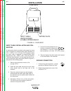
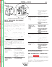
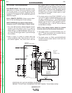
1. POWER SWITCH: Turns output
power ON and OFF. This switch
also controls auxiliary power
available through the 14-pin Wire
Feeder Receptacle.
2A. BACKGROUND CURRENT OUTPUT CONTROL:
The output current is switched to the
Background level at the conclusion of the
preceding Peak Current pulse. This knob
allows preset adjustment of the amplitude
of the background current up to 125
amperes.
2B. BACKGROUND CURRENT DISPLAY METER:
This is a digital meter for displaying the
preset Background Current. This meter
displays in 1 amp increments. This meter
does not indicate the actual welding cur-
rent, only the preset current.
3A. PEAK CURRENT OUTPUT CONTROL: The
beginning portion of the welding arc is a
pulse of current referred to as Peak
Current. This knob allows preset adjust-
ment of the amplitude of the peak current
up to 450 amperes.
3B. PEAK CURRENT DISPLAY METER: This
is a digital meter for displaying the preset
Peak Current. This meter displays in 1
amp increments. This meter does not indi
-
cate actual welding current only the preset
current.
4. HOT START CONTROL POTENTIOMETER:
“Hot Start” provides approximately 25% to
50% more current during the initial start of
the weld for improved arc starting and bead
appearance. This control adjusts the dura-
tion of this “Hot Start” current. The control range is
from 0 to 10, where 0 corresponds to the zero or no
“Hot Start”, and 10 is maximum for a “Hot Start” last-
ing for about four (4) seconds.
5. TAILOUT: Alters the current waveform to increase
deposit rate and travel speed. The Minimum setting
sets STT II to the original STT waveform. As tailout
is increased peak and Background current may
need to be reduced to maintain optimum perfor-
mance.
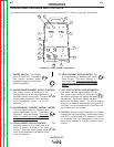
OPERATIONAL FEATURES AND CONTROLS
All operator controls are located on the case front of the Invertec STT II. Refer to Figure B.1 for locations.
FIGURE B.1 CASE FRONT CONTROLS
4
1
2
3
7
6
8
10
9
11
14
15
12
13
5
ON
OFF
A
A
V