


Return to Section TOC Return to Section TOC Return to Section TOC Return to Section TOC
Return to Master TOC Return to Master TOC Return to Master TOC Return to Master TOC
TROUBLESHOOTING & REPAIR
F-72 F-72
INVERTEC STT
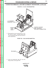
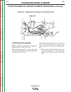
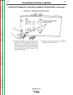
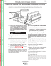
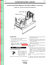
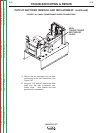
19. Install the new capacitor and tighten the two
7/16” hex bolts to a torque of 55 inch-pounds
(6 Nm). Tighten these bolts in increments of
10 inch-pounds, alternating between the two
bolts. Capacitor installation is complete. See
Figure F.38.
Proper capacitor polarity must be noted when
attaching the capacitor to the switch board
assembly.
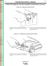
20. Install the switch board and capacitor
assembly into the machine. Take special
care that ALL insulators and sleevings are in
their proper positions. See Figure F.38.
21. Install the lower tray assembly and all previ-
ously disconnected loads and plugs.
22. Perform the Test After Repair of Switch
Boards and/or Capacitors.
NOTE: Always make sure that the switch boards
are changed in matched pairs. Never mix an old
style switch board (different part number) with
new style (new part number).
INPUT FILTER CAPACITOR CONDITIONING
If the machine will not produce output when
turned on and the following two conditions exist:
The machine is connected to operate at an
input voltage of 380 VAC or higher and
Power has not been applied to the machine for
a long period of time (many months). Then. . .
The Input Filter Capacitor Protection Circuit could
have been activated and prevented output. This
means the Input Filter Capacitors must be condi-
tioned.
The Input Filter Capacitor Protection Circuit mon-
itors the voltage across input filter capacitors C1
and C2. When it senses an overvoltage condi-
tion, the protection circuit will prevent the
machine from operating.
To condition the Input Filter Capacitors:
1. Turn main power OFF.
2. Remove any load and do not load machine
until conditioning procedure is complete.
3. Turn main power ON.
4. Let the unloaded machine sit for 30 minutes.
5. Turn main power OFF.
6. Turn main power ON.
NOTE: The machine should be ready to operate,
and the protection circuit should have automati-
cally reset once the capacitors have been condi-
tioned and capacitor voltage has reached the
acceptable operating level.
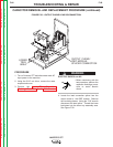
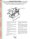
FIGURE F.38 – COMPLETE SWITCH BOARD ASSEMBLY READY FOR INSTALLATION
CAPACITOR REMOVAL AND REPLACEMENT PROCEDURE (continued)
CAUTION