


Return to Section TOC Return to Section TOC Return to Section TOC Return to Section TOC
Return to Master TOC Return to Master TOC Return to Master TOC Return to Master TOC
TROUBLESHOOTING & REPAIR
F-66 F-66
INVERTEC STT
CAPACITOR REMOVAL AND REPLACEMENT PROCEDURE (continued)
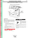
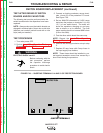
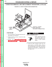
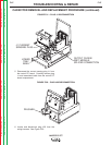
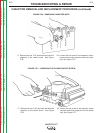
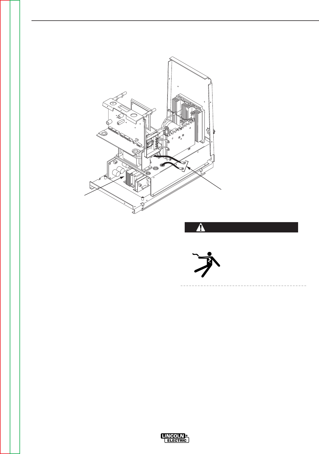
FIGURE F.30 – OUTPUT CHOKE LEAD DISCONNECTION
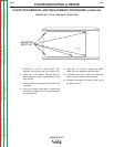
LOWER
TRAY
AREA
OUTPUT CHOKE/
IGBT MODULE
SPLICED CONNECTION
PROCEDURE
1. Turn off Invertec STT and disconnect main AC
input power to the machine.
2. Using the 5/16" nut driver, remove the case
wraparound cover.
3. Perform the Input Filter Capacitor
Discharge Procedure. See the Maintenance
section.
ELECTRIC SHOCK can kill.
• Before continuing with the
test procedure, perform the
capacitor discharge proce-
dure to avoid electric
shock.
4. Locate the lead connection splice from the
output choke to the IGBT module. Remove
the insulating sleeve. Using the 7/16" wrench
disconnect the lead splice. Thread the lower
lead down into the lower tray assembly area.
See Figure F.30.
WARNING