


Features
Standard
Specifications
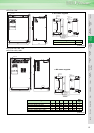
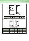
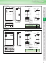
Outline
Dimension
Drawings
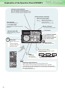
Operation
Panel
Protective
Functions
OptionsInstructionsMotorCompatibilityWarrantyInquiry
Peripheral Devices
Why energy
savings?
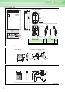
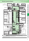
Terminal Connection
Diagram
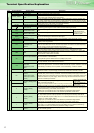
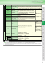
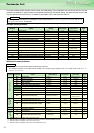
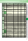
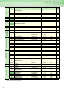
Terminal Specification
Explanation
Parameter
List
Explanations
of
Parameters
16
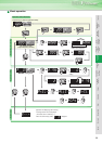
CAUTION
⋅
To prevent a malfunction due to noise, keep the signal cables more than 10cm away from the power cables.
⋅ Be sure to use the inverter and motor after grounding (earthing) them.
⋅ This connection diagram assumes that the control circuit is sink logic (initial setting). Refer to the instruction manual for the
connection in the case of source logic.
Three-phase AC
power supply
MCCB
Jumper
R/L1
S/L2
T/L3
R1/L11
S1/L21
PC
10E(+10V)
10(+5V)
2
3
1
1
4
Control input signals (No voltage input allowed)
Jumper
Motor
Relay output 1
(Alarm output)
C1
B1
A1
U
V
W
AM
5
*1
Main circuit terminal
Control circuit terminal
MC
Main circuit
Control circuit
C2
B2
A2
Relay output 2
Relay output
IM
AU
PTC
TXD+
TXD-
RXD+
RXD-
SG
SINK
SOURCE
Terminal functions
vary with the output
terminal assignment
(Pr. 195, Pr. 196)
Terminal functions
vary with the output
terminal assignment
(Pr. 190 to Pr. 194)
Terminal functions
vary with the input
terminal assignment
(Pr. 178 to Pr. 189)
*3
STF
STR
STOP
RH
RM
RL
JOG
RT
MRS
RES
AU
CS
SD
RUN
SU
IPF
OL
FU
SE
Connector for
with/without
EMC filter
ON
OFF
VCC
Frequency setting signal (Analog)
Frequency setting
potentiometer
1/2W1k
Ω
Auxiliary input
(+)
(-)
2
(Analog common)
0 to 5VDC
0 to 10VDC
selected
4 to 20mADC
*
4
5
PU
connector
Terminal 4 input
(Current input)
Terminating
resistor
Connector
for plug-in option
connection
*
5. It is recommended to use
2W1kΩ when the
frequency setting signal is
changed frequently.
(+)
(-)
0 to 5VDC
0 to 10VDC
selected
*
4
GND
RS-485 terminals
Data transmission
Data reception
4 to 20mADC
*
4
selected
0 to ±5VDC
0 to
±
10VDC
(-)
(+)
(0 to 10VDC)
Analog signal output
Frequency detection
Open collector output common
Sink
/source common
Running
Up to frequency
Instantaneous
power failure
Overload
Open collector output
Terminal 4 input selection
(Current input selection)
Selection of automatic restart
after instantaneous
power failure
Output stop
Reset
*3. AU terminal
can be used
as PTC input
terminal.
Middle speed
High speed
Low speed
Jog mode
Second function selection
Multi-speed
selection
Forward
rotation
start
Reverse
rotation
start
Start self-holding selection
PR*7
PX*7
Jumper
*7.
*5
*
4. Terminal input
specifications can be
changed by analog input
specifications switchover
(Pr. 73, Pr. 267).
(Permissible load
current 100mA)
5V
*2. To supply power to the
control circuit separately,
remove the jumper across
R1/L11 and S1/L21.
*2
Do not use PR and PX terminals.
Please do not remove the jumper
connected to terminal PR and PX.
N/-
P/+
Option connector 1
P1
Resistor unit
(Option)
Brake unit
(Option)
CN8
*6
Sink logic
Earth
(Ground)
Earth
(ground)
cable
Earth
(ground)
+-
Indicator
(Frequency meter, etc.)
Moving-coil type
1mA full-scale
Calibration
resistor
*
9
SD
FM
24VDC power supply
(Common for external power supply transistor)
Contact input common
*1. DC reactor (FR-HEL)
Be sure to connect the DC reactor
supplied with the 75K or more.
When a DC reactor is connected
to the 55K or less, remove the
jumper across P1-P/+.
*6. A CN8 connector is
provided with the
75K or more.
*
9. It is not necessary
when calibrating the
indicator from the
operation panel.
*8.
The 200V class 0.75K and 1.5K
are not provided with the ON/OFF
connector of the EMC filter.
*8
Terminal Connection Diagram