


Features
Standard
Specifications
Outline
Dimension
Drawings
Operation
Panel
Protective
Functions
OptionsInstructionsMotorCompatibilityWarrantyInquiry
Peripheral Devices
Why energy
savings?
Terminal Connection
Diagram
Terminal Specification
Explanation
Parameter
List
Explanations
of
Parameters
46
indicates simple mode parameters and indicates extended parameters. When setting parameters, refer to the instruction manual (applied) and understand instructions.
Pr.
Pr.
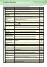
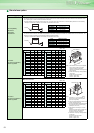
⋅ The following gives the items which can be monitored by the
cumulative saving power monitor (Pr. 52 = "51").
(The cumulative power monitor data digit can be shifted to the
right by the number set in Pr. 891 Cumulative power monitor digit
shifted times.)
* The increments vary according to the inverter capacity. (55K or less/75K or
more)
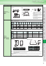
The operation panel and parameter unit can be used to calibrate
the full scales of the terminals FM and AM.
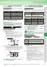
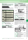
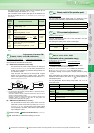
(1) FM terminal calibration (C0(Pr.900))
⋅ The terminal FM is preset to output pulses. By setting the
Calibraton parameter C0 (Pr. 900), the meter connected to the
inverter can be calibrated by parameter setting without use
of a calibration resistor.
⋅ Using the pulse train output of the terminal FM, a digital
display can be provided by a digital counter. The monitor
value is 1440 pulses/s output at the full-scale value of Pr. 54
FM terminal function selection.
*1 Not needed when the operation panel (FR-DU07) or parameter unit (FR-
PU04) is used for calibration.
Used when calibration must be made near the frequency meter for such a
reason as a remote frequency meter.
However, the frequency meter needle may not deflect to full-scale if the
calibration resistor is connected. In this case, use this resistor and
operation panel or parameter unit together.
(2) AM terminal calibration (C1(Pr.901))
⋅ The AM terminal is factory-set to output 10VDC in the full-
scale state of each monitor item. By setting the calibration
parameter C1 (Pr. 901), the ratio (gain) of the output voltage
can be adjusted to the meter scale. Note that the maximum
output voltage is 10VDC.
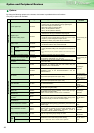
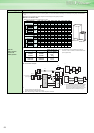
You can make the buzzer "beep" when you press key of the
operation panel (FR-DU07) and parameter unit (FR-PU04).
Contrast adjustment of the LCD of the parameter unit (FR-
PU04) can be performed.
Decreasing the setting value makes contrast light.
Set “1” in Pr.CL Parameter clear to initialize all parameters.
(Calibration parameters are not cleared.)*
Set “1” in ALLC All parameter clear to initialize all parameters. *
Set “1” in Er.CL Alarm history clear to clear alarm history. *
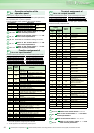
Parameter settings can be copied to multiple inverters by using
PCPY.
When parameters are copied to the 75K or more inverter from
the 55K or less inverter or vice versa, an alarm appears on
the operation panel.
For the parameters whose setting range differ, set
Pr.989 as
below after reset.
* Parameters are not cleared when "1" is set in Pr.77 Parameter write selection.
Energy
Saving
Monitor
Item
Description and Formula Increments
Power
saving
amount
Power saving is added up per hour.
Σ (Power saving × ∆t)
0.01kWh/
0.1kWh*
Power
saving
amount
charge
Power saving amount represented in terms of
charge
Power saving amount × Pr. 896
0.01/0.1*
Annual
power
saving
amount
Estimated value of annual power saving amount
× 24 × 365 ×
0.01kWh/
0.1kWh*
Annual
power
saving
amount
charge
Annual power saving amount represented in
terms of charge
Annual power saving amount × Pr. 896
0.01/0.1*
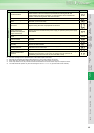
Adjustment of terminal FM
and AM (calibration)
C0(Pr.900) FM terminal calibration C1(Pr.901) AM terminal calibration
C2(902) to C7(905)
Refer to the section about
Pr. 125, Pr. 126
989
Parameter for manufacturer setting. Do not set.
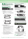
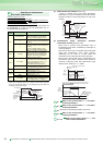
Power saving amount
Operation time during
power saving totalization
Pr.899
100
Pr.
C0(900), C1(901)
8VDC
T2
T1
Pulse width T1: Adjust using calibration parameter C0
Pulse cycle T2: Set with Pr. 55 (frequency monitor)
Set with Pr.56 (current monitor)
(Digital indicator)
(-)
1440 pulse/s(+)
FM
SD
Indicator
1mA full-scale
analog meter
(+)
1mA
FM
SD
Calibration
resistor
*1
(-)
Pr.
Pr.
Buzzer control of the operation panel
Pr.990 PU buzzer control
Pr.990 Setting Description
0 Without buzzer
1(initial value) With buzzer
PU contrast adjustment
Pr.991 PU contrast adjustment
Pr.991 Setting Description
0 to 63
0 : Light
↓
63 : Dark
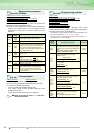
Parameter clear, parameter copy
Pr.989 Parameter copy alarm release
Pr.CL Parameter clear ALLC All parameter clear
Er.CL Alarm history clear PCPY Parameter copy
55K or less 75K or more
Pr.989 setting
10 100
PCPY
Setting
Description
0 Cancel
1 Copy the source parameters in the operation panel.
2
Write the parameters copied to the operation panel to the
destination inverter.
3 Verify parameters in the inverter and operation panel.
Pr.
990
Pr.
991
Pr.
989, CL, ALLC, Er.CL, PCPY