


Features
Standard
Specifications
Outline
Dimension
Drawings
Operation
Panel
Protective
Functions
OptionsInstructionsMotorCompatibilityWarrantyInquiry
Peripheral Devices
Why energy
savings?
Terminal Connection
Diagram
Terminal Specification
Explanation
Parameter
List
Explanations
of
Parameters
40
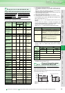
indicates simple mode parameters and indicates extended parameters. When setting parameters, refer to the instruction manual (applied) and understand instructions.
Pr.
Pr.
You can switch the display language of the parameter unit (FR-
PU04) to another.
The output current during inverter running can be detected and
output to the output terminal.
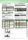
(1) Output current detection
(Y12 signal, Pr. 150, Pr. 151, Pr. 166, Pr. 167)
⋅ The output current detection function can be used for
excessive torque detection, etc.
⋅ If the output current remains higher than the Pr. 150 setting
during inverter operation for longer than the time set in Pr.
151, the output current detection signal (Y12) is output from
the inverter's open collector or relay output terminal.
(2) Zero current detection (Y13 signal, Pr. 152, Pr. 153)
⋅ If the output current remains lower than the Pr. 152 setting
during inverter operation for longer than the time set in Pr.
153, the zero current detection (Y13) signal is output from
the inverter's open collector or relay output terminal.
You can select the second function using the external terminal
(RT signal).
You can also set the RT signal operation condition (reflection time).
⋅ Functions that can be set as second functions
Parameter which can be read from the operation panel and parameter
unit can be restricted.
In the initial setting, only the simple mode parameters are displayed.
(1) Display of simple mode parameters and extended
parameters (
Pr.160
)
⋅ When Pr. 160 = "9999" (initial value), only the simple mode
parameters can be displayed on the operation panel (FR-
DU07) and parameter unit (FR-PU04).
⋅ When “0” is set in Pr. 160, simple mode parameters and
extended parameters can be displayed.
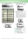
(2) User group function (Pr.160, Pr.172 to Pr.174)
⋅ The user group function is designed to display only the
parameters necessary for setting.
⋅ From among all parameters, a maximum of 16 parameters can
be registered to a user group. When Pr. 160 is set in "1", only the
parameters registered to the user group can be accessed. (The
parameters not registered to the user group cannot be read.)
⋅ To register a parameter to the user group, set its parameter
number to Pr. 173.
⋅ To delete a parameter from the user group, set its parameter
number to Pr. 174. To batch-delete the registered parameters, set
Pr. 172 in "9999".
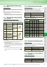
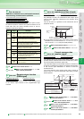
Parameter unit display language
selection
Pr.145
PU display language selection
Pr.145 Setting Description
0 (initial value) Japanese
1 English
2 German
3 French
4 Spanish
5 Italian
6 Swedish
7 Finnish
148, 149
Refer to the section about Pr. 22 and
other relevant parameters.
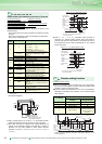
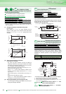
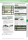
Detection of output current (Y12 signal) detection
of zero current (Y13 signal)
Pr.150 Output current detection level
Pr.151 Output current detection signal delay time
Pr.152 Zero current detection level Pr.153 Zero current detection time
Pr.166 Output current detection signal retention time
Pr.167 Output current detection operation selection
154
Refer to the section about Pr. 22 and other
relevant parameters.
Pr.
145
Pr.
Pr.
150 to 153, 166, 16
7
Time
Pr.150
OFF
ON
OFF
Output current
detection signal
(Y12)
Pr.166
Minimum 100ms
(initial value)
Output current
Pr.166 9999, Pr.167 = 0
Pr.151
OFF ON
Start signal
Tim
e
Output
current
OFF
ON
Zero current
detection time
(Y13)
Pr. 153
Detection time
Pr. 153
Detection time
Pr.152
OFF
ON
0[A]
100ms
*
Pr.152
* Once turned on, the zero current detection time
(Y13) signal is held on for at least 100ms.
Pr.
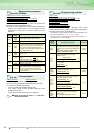
Selection of action conditions of
the second function signal (RT)
Pr.155 RT signal reflection time selection
Pr.155 Setting Description
0 (initial value)
This function is immediately made valid with on
of the RT signal.
10
This function is valid only during the RT signal
is on and constant speed operation. (invalid
during acceleration/deceleration)
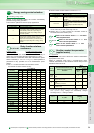
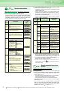
Function
First Function
Parameter Number
Second Function
Parameter Number
Torque boost Pr.0 Pr.46
Base frequency Pr.3 Pr.47
Acceleration time Pr.7 Pr.44
Deceleration time Pr.8 Pr.44, Pr.45
Electronic thermal O/L
relay
Pr.9 Pr.51
Stall prevention Pr.22 Pr.48, Pr.49
156, 157
Refer to the section about Pr. 22 and
other relevant parameters.
158
Refer to the section about Pr. 54 and other
relevant parameters.
159
Refer to the section about Pr. 135 and other
relevant parameters.
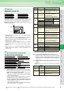
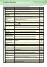
Display of applied parameters and user group function
Pr.172 User group registered display/batch clear
Pr.173 User group registration Pr.174 User group clear
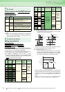
Pr. 160
Setting
Description
9999
(initial
value)
Only the simple mode parameters can be displayed.
0 Simple mode+extended parameters can be displayed.
1 Only parameters registered to the user group can be displayed.
Pr.
155
Pr.
Pr.
Pr.
Pr.
160
Pr.
172 to 174
Pr.160 User group read selection