31
indicates simple mode parameters and indicates extended parameters. When setting parameters, refer to the instruction manual (applied) and understand instructions.
Pr.
Pr.
Use the high power factor converter (FR-HC) to reduce
harmonics, improve the power factor, or continuously use the
regenerative mode.
For the 75K or more, use the brake unit MT-BU5 or BR5 when the
regenerative brake duty is need to be increased due to frequent
starts and stops. Use the high power factor converter MT-HC to
reduce harmonics, improve the power factor, or continuously use
the regenerative mode.
<55K or less>
<75K or more>
* Pr.70 Special regenerative brake duty can be set for the 75K or more inverter.
When it is desired to
avoid resonance
attributable to the
natural frequency of a
mechanical system,
these parameters allow
resonant frequencies to
be jumped.
Up to three areas may be set, with the jump frequencies set to
either the top or bottom point of each area.
The value set to 1A, 2A or 3A is a jump point and operation in the
jump zone is performed at these frequencies.
Frequency jump is not performed if the initial value is set to "9999".
During acceleration/deceleration, the running frequency within the
set area is valid.
You can change the PU (FR-DU07) monitor display or frequency
setting to motor speed or machine speed.
When the running speed monitor is selected, each monitor and
setting are determined according to the combination of Pr. 37 and
Pr. 144. (The units within the thick frame are the initial values.)
*1 Motor speed r/min conversion formula
....... Frequency × 120/number of motor poles (Pr. 144)
Machine speed conversion formula
......Pr. 37 × frequency/60Hz
For Pr. 144 in the above formula, the value is “Pr. 144-100” when “102 to
110” is set in Pr. 144 and the value is “4” when Pr. 37=0 and Pr.144=0.
*2 The increments for Hz are 0.01Hz, machine speed are 1m/min and r/min
are 1r/min
.
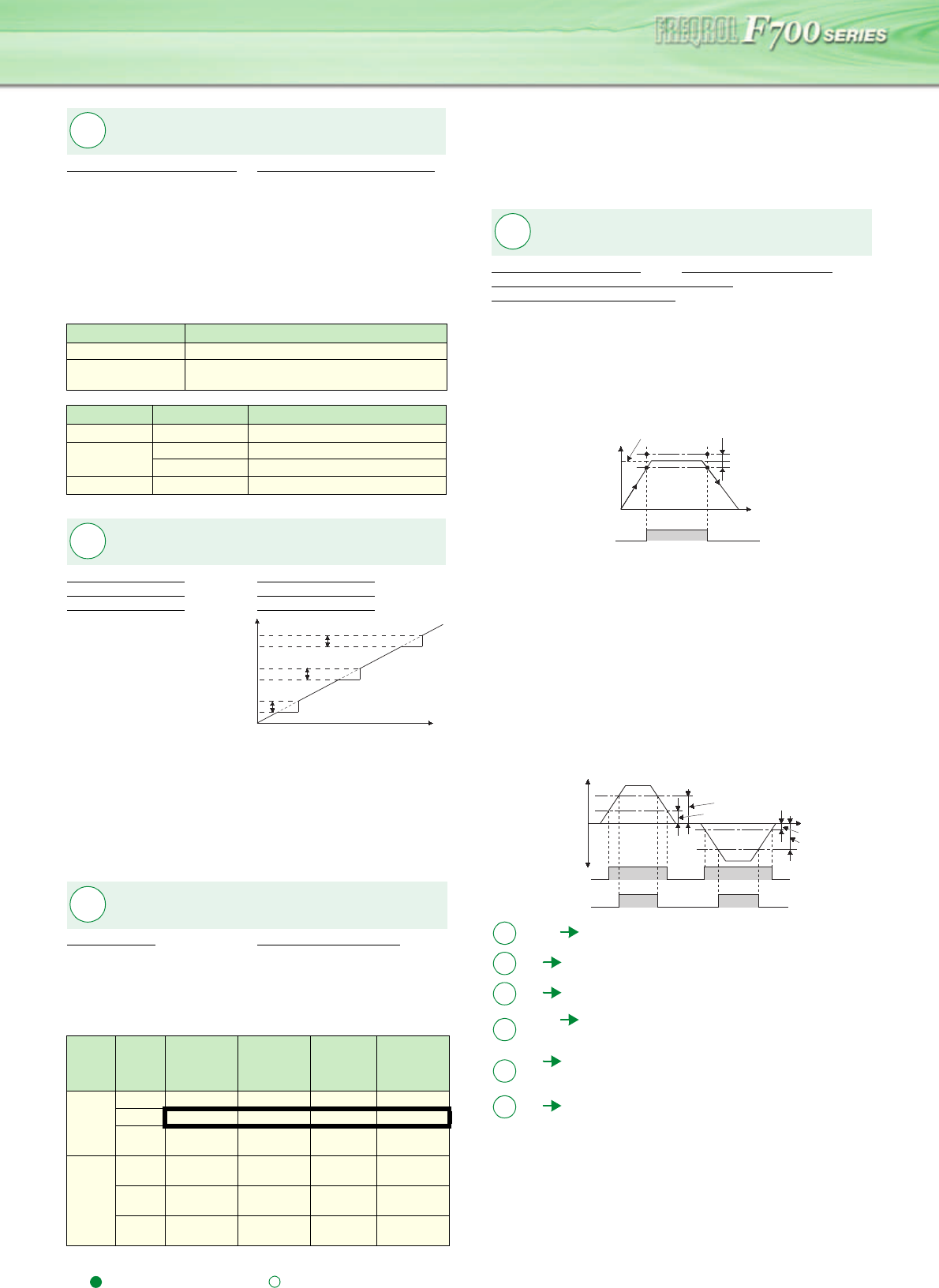
The inverter output frequency is detected and output at the
output signals.
If the set frequency is considered as 100%, output frequency can
be adjusted between ±1% and ±100% with Pr. 41.
This parameter can be used to ensure that the running frequency
has been reached to provide the operation start signal etc. for
related equipment.
When the output frequency reaches or exceeds the setting of Pr.
42, the output frequency detection signal (FU) is output.
This function can be used for electromagnetic brake operation,
open signal, etc.
When the detection frequency is set in Pr. 43, frequency detection
for reverse rotation use only can also be set. This function is
effective for switching the timing of electromagnetic brake
operation between forward rotation (rise) and reverse rotation
(fall) during vertical lift operation, etc.
When outputting a frequency detection signal besides the FU
signal, set the detection frequency to Pr. 50 . The FU2 signal is
output when the output frequency reaches or exceeds the Pr. 50
setting.
Selection of
regeneration unit
Pr.30 Regenerative function selection Pr.70 Special regenerative brake duty *
Pr.30 Setting Regeneration Unit
0 (initial value) Brake unit (FR-BU, BU)
2
High power factor converter (FR-HC),
power regeneration common converter (FR-CV)
Pr.30 Setting Pr.70 Setting * Regeneration Unit
0 (initial value) Not used
1
0% Power regeneration converter (MT-RC)
10% Brake unit (MT-BU5)
2 High power factor converter (MT-HC)
Avoid mechanical resonance
points (frequency jump)
Pr.31 Frequency jump 1A Pr.32 Frequency jump 1B
Pr.33 Frequency jump 2A Pr.34 Frequency jump 2B
Pr.35 Frequency jump 3A Pr.36 Frequency jump 3B
Speed display and speed
setting
Pr.37 Speed display Pr.144 Speed setting switchover
Pr. 37
Setting
Pr. 144
Setting
Output
Frequency
Monitor
Set
Frequency
Monitor
Running
Speed
Monitor
Frequency
Setting
Parameter
Setting
0
0 Hz Hz r/min *1 Hz
2 to 10 Hz Hz r/min *1 Hz
102 to
110
r/min *1 r/min *1 r/min *1 r/min *1
1 to
9998
0 Hz Hz
Machine
speed
*1
Hz
2 to 10
Machine
speed
*1
Machine
speed
*1
Machine
speed
*1
Machine
speed
*1
102 to
110
Hz Hz r/min *1 Hz
Pr.
30, 70
Pr.
31 to 36
Pr.31
Frequency jump
Pr.32
Pr.33
Pr.34
Pr.35
Pr.36
Set frequency (Hz)
Pr.
37, 144
Detection of output frequency (SU,
FU, FU2 signal)
Pr.41 Up-to-frequency sensitivity Pr.42 Output frequency detection
Pr.43 Output frequency detection for reverse rotation
Pr.50 Second output frequency detection
44, 45
Refer to the section about Pr.7, Pr.8
46
Refer to the section about Pr. 0.
47
Refer to the section about Pr. 3.
48, 49
Refer to the section about Pr. 22 and other
relevant parameters.
50
Refer to the section about Pr. 41 and other
relevant parameters.
51
Refer to the section about Pr. 9.
Pr.
41 to 43, 50
Output frequency
(Hz)
ON
Running frequency Adjustment
range
Pr.41
SU
Time
OFFOFF
Output
frequency
Forward
rotation
Reverse
rotation
Time
Output frequency
(Hz)
ON ON
OFF
OFF OFF OFF
OFFOFF
ON ON
FU
FU2
Pr.5
Pr.43
Pr.50
Pr.42
Pr.
Pr.
Pr.
Pr.
Pr.
Pr.


