


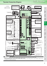

5
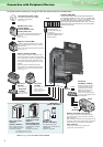
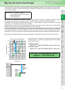
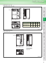
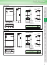
Peripheral devices necessary for driving the FR-F700 series inverter are indicated below.
Refer to page 49 for the option list and details.
PLC
Three-phase AC power supply
AC reactor
(FR-HAL)
DC reactor
(FR-HEL)
R/L1 S/L2 T/L3
P/+
N/-P/+
P1
UVW
Moulded case circuit
breaker (MCCB)
or earth leakage circuit
breaker (ELB), fuse
Magnetic contactor(MC)
RS-485 terminal block
Noise filter
(FR-BSF01, FR-BLF)
Motor
Devices connected to the output
Use within the permissible power supply
specifications of the inverter.
The regenerative braking
capability of the inverter can be
exhibited fully.
Install this as required.
Install the magnetic contactor to ensure safety.
Do not use this magnetic contactor to start and
stop the inverter.
Doing so will cause the inverter life to be shorten.
The inverter can be
connected with computers
such as PLC.
It supports Mitsubishi inverter
protocol and Modbus-RTU
(binary) protocol.
Do not install a power factor correction capacitor,
surge suppressor or radio noise filter on the output
side of the inverter.
When installing a moulded case circuit breaker on the
output side of the inverter, contact each manufacturer
for selection of the moulded case circuit breaker.
Power supply harmonics
can be greatly suppressed.
Install this as required.
Greater braking capability
is obtained.
Install this as required.
The breaker must be selected carefully since
an in-rush current flows in the inverter at
power on.
Install a noise filter to reduce
the electromagnetic noise
generated from the inverter.
Effective in the range from
about 1MHz to 10MHz.
When more wires are passed
through, a more effective result
can be obtained.
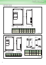
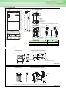
Power regeneration
common converter
(FR-CV
*1)
Power regeneration
converter (MT-RC
*2)
Resistor unit
(FR-BR
*1, MT-BR5*2)
Brake unit
(FR-BU
*1, MT-BU5*2)
High power factor
converter
(FR-HC
*1, MT-HC*2)
P/+
P/+
PR
PR
Noise filter
(FR-BLF)
It is not necessary
for the 55K or less.
*1 Compatible with the 55K or less.
*2 Compatible with the 75K or more.
For the 75K or more, a DC
reactor is supplied.
Always install the reactor.
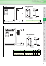
Earth
(Ground)
Earth
(Ground)
Earth (Ground)
To prevent an electric shock, always earth
(ground) the motor and inverter.
Reactor (FR-HAL, FR-HEL)
Reactors (option) should be used when power
harmonics measures are taken, the power factor
is to be improved or the inverter is installed near a
large power supply system (1000kVA or more).
The inverter may be damaged if you do not use
reactors.
Select the reactor according to the model.
For the 55K or less, remove the jumpers across
terminals P/+-P1 to connect to the DC reactor.
(Refer to page 7.)
(Refer to page 57.)
(Refer to page 57.).
(Refer to page 51.).
(Refer to page 51.)
Inverter (FR-F700)
The life of the inverter is influenced by ambient temperature.
The ambient temperature should be as low as possible within
the permissible range. (Refer to page 8.) This must be noted
especially when the inverter is installed in an enclosure.
Wrong wiring might lead to damage of the inverter. The control
signal lines must be kept fully away from the main circuit to
protect them from noise.
(Refer to page 51.)
Connection with Peripheral Devices