


39
indicates simple mode parameters and indicates extended parameters. When setting parameters, refer to the instruction manual (applied) and understand instructions.
Pr.
Pr.
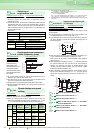
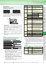
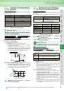
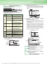
You can set the magnitude (slope) of the output frequency as
desired in relation to the frequency setting signal (0 to 5VDC, 0 to
10V or 4 to 20mA).
(1) Change the frequency at maximum analog input.
(
Pr.125, Pr.126
)
Set a value in Pr. 125 (Pr. 126) when changing only the
frequency setting (gain) of the maximum analog input power
(current). (C2 (Pr. 902) to C7 (Pr. 905) setting need not be
changed)
(2) Analog input bias/gain calibration
(C2(Pr.902) to C7(Pr.905))
⋅ The "bias" and "gain" functions are used to adjust the
relationship between the input signal entered from outside
the inverter to set the output frequency, e.g. 0 to 5V, 0 to 10V
or 4 to 20mADC, and the output frequency.
⋅ Set the bias frequency of terminal 2 input using C2(Pr. 902).
(Factory-set to the frequency at 0V)
⋅ Using Pr. 125 , set the output frequency relative to the
frequency command voltage (current) set in Pr. 73 Analog
input selection.
⋅ Set the bias frequency of the terminal 4 input using C5(Pr.
904).
(Factory-set to the frequency at 4mA)
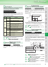
⋅ Using Pr. 126 , set the output frequency relative to 20mA of
the frequency command current (4 to 20mA).
(3) Analog input display unit changing (Pr. 241)
⋅ You can change the analog input display unit (%/V/mA) for
analog input bias/gain calibration.
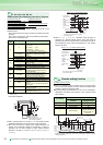
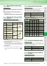
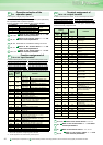
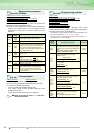
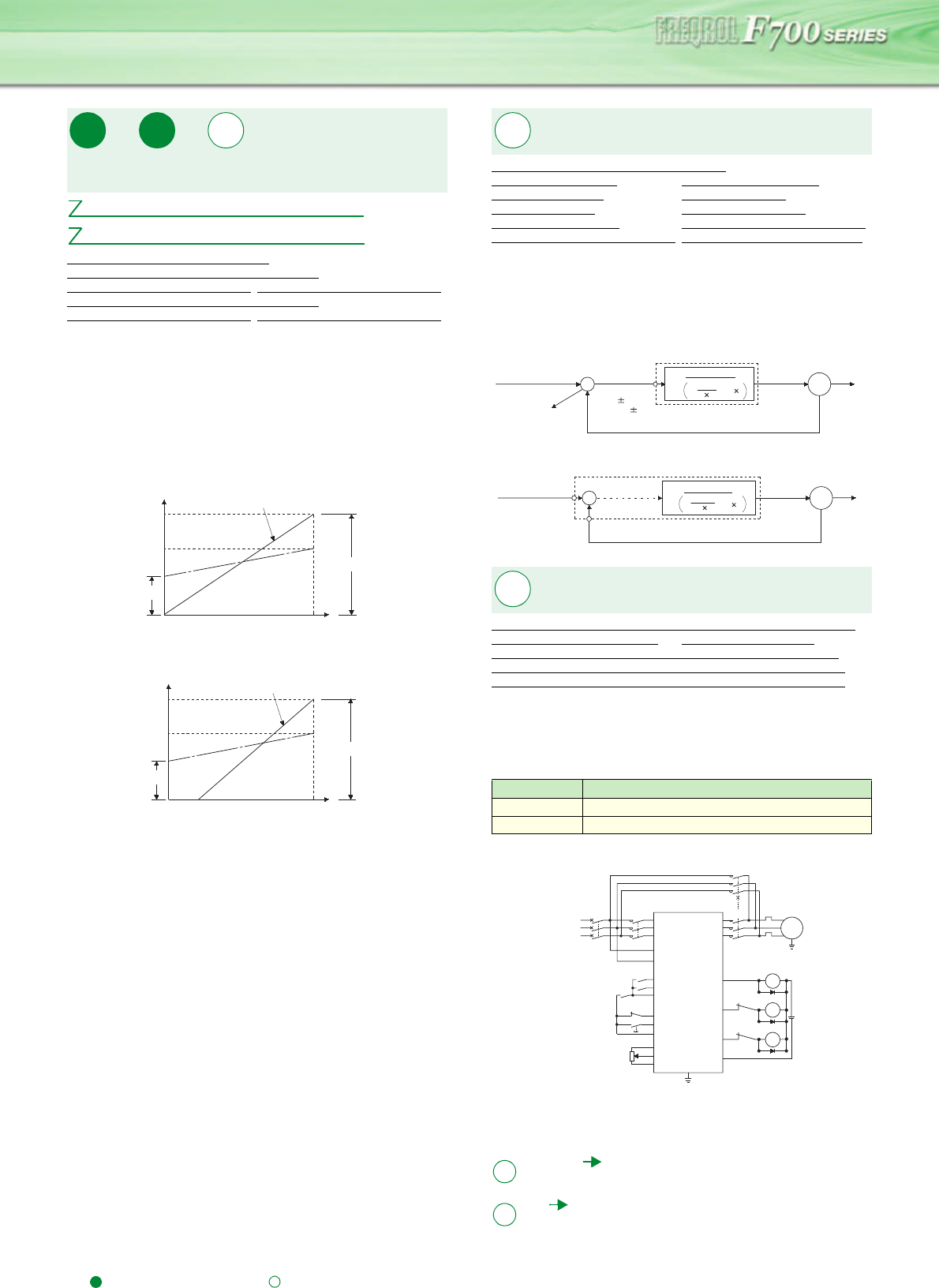
The inverter can be used to exercise process control, e.g. flow
rate, air volume or pressure.
The terminal 2 input signal or parameter setting is used as a set point
and the terminal 4 input signal used as a feedback value to constitute
a feedback system for PID control.
⋅ Pr.128 ="10, 11" (Deviation value signal input)
⋅ Pr.128 ="20, 21" (Measured value input)
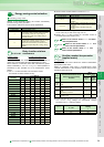
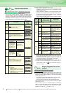
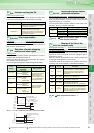
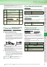
The complicated sequence circuit for commercial power supply-
inverter switchover is built in the inverter. Hence, merely
inputting the start, stop or automatic switchover selection signal
facilitates the interlock operation of the switchover magnetic
contactor.
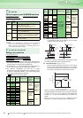
Sink logic type, Pr.185 = "7", Pr.192 = "17", Pr.193 = "18", Pr.194 = "19"
*1 Take caution for the capacity of the sequence output terminal.
*2 When connecting a DC power supply, insert a protective diode.
*3 The used terminal changes depending on the setting of Pr. 180 to Pr. 189
(input terminal function selection).
Analog input frequency change and voltage, current input and
frequency adjustment (calibration)
Pr. 241 Analog input display unit switchover
C2(Pr.902) Terminal 2 frequency setting bias frequency
C3(Pr.902)
Terminal 2 frequency setting bias
C4(Pr.903)
Terminal 2 frequency setting gain
C5(Pr.904) Terminal 4 frequency setting bias frequency
C6(Pr.904)
Terminal 4 frequency setting bias
C7(Pr.905)
Terminal 4 frequency setting gain
Pr.
125
Pr.
126
Pr.
241, C2(902) to C7(905)
Pr.125 Terminal 2 frequency setting gain frequency
Pr.126 Terminal 4 frequency setting gain frequency
Output frequency
(Hz)
Pr.125
0
0
Frequency setting signal
100%
10V
Initial value
Bias
Gain
05V
C2
(Pr.902)
(Pr.902) (Pr.903)
C3 C4
60Hz
Output frequency
(Hz)
Pr.126
0
Frequency setting signal
100%
Initial value
Bias
Gain
0
20
4 20mA
C5
(Pr.904)
C6
(Pr.904) (Pr.905)
C7
60Hz
PID control
Pr.127 PID control automatic switchover freqeuncy
Pr.128 PID action selection Pr.129 PID proportional band
Pr.130 PID integral time Pr.131 PID upper limit
Pr.132 PID lower limit Pr.133 PID action set point
Pr.134 PID differential time Pr.575
Output interruption detection time
Pr.576
Output interruption detection level
Pr.577 Output interruption release level
Switch between the inverter operation and
commercial power-supply operation to use
Pr.135 Commercial power-supply switchover sequence output terminal selection
Pr.136 MC switchover interlock time Pr.137 Waiting time at a start
Pr.138 Commercial power-supply operation switchover selection at an alarm
Pr.139 Automatic switchover frequency between inverter and commercial power-supply operation
Pr.159 Automatic switchover ON range between commercial power-supply and inverter operation
Pr135 Setting Description
0 (initial value) Without commercial power-supply switchover sequence
1 With commercial power-supply switchover sequence
Commercial power-supply switchover sequence connection diagram
140 to 143
Refer to the section about Pr. 29 and
other relevant parameters.
144
Refer to the section about Pr. 37 and other
relevant parameters.
Pr.
127 to 134, 575 to 57
7
+
-
IM
Deviation signal
Feedback signal (measured value)
Ti S
1
1+
+Td S
Kp
PID operation
To outside
Set point
Inverter circuit
Motor
Terminal 1
0 to 10VDC
(0 to 5V)
Kp: Proportionality constant Ti: Integral time S: Operator Td: Differential time
Manipulated
variable
+
-
IM
Ti S
Kp 1+ +Td S
1
PID operation
Pr. 133 or
terminal 2
Set point
Inverter circuit
Motor
Feedback signal (measured value)
Terminal 4
Kp: Proportionality constant Ti: Integral time S: Operator Td: Differential time
Manipulated
variable
0 to 5VDC
(0 to 10V, 4 to 20mA)
4 to 20mADC (0 to 5V, 0 to 10V)
Pr.
135 to 139, 159
Inverter start
(forward rotation)
MC1
R/L1
S/L2
T/L3
STF
R1/L11
S1/L21
CS
MRS
RES
10
2
5
U
V
W
External
thermal relay
IM
(MC1)IPF
(MC2)OL
SE
MC3
MC2
24VDC
MC
1
External
thermal reset
Frequency
setting signal
(MC3)FU
Inverter/commercial
power-supply switchover
Operation interlock
MC
2
MC
3
*3
*1
*2
*1
*1
JOG(OH)
MCCB
MC2
MC3
SD
Pr.
Pr.