


Features
Standard
Specifications
Outline
Dimension
Drawings
Operation
Panel
Protective
Functions
OptionsInstructionsMotorCompatibilityWarrantyInquiry
Peripheral Devices
Why energy
savings?
Terminal Connection
Diagram
Terminal Specification
Explanation
Parameter
List
Explanations
of
Parameters
32
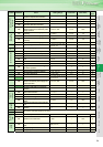
indicates simple mode parameters and indicates extended parameters. When setting parameters, refer to the instruction manual (applied) and understand instructions.
Pr.
Pr.
The monitor to be displayed on the main screen of the operation
panel (FR-DU07) / parameter unit (FR-PU04) can be selected.
*1 Selected by the parameter unit(FR-PU04)
*2 The cumulative energization time and actual operation time are
accumulated from 0 to 65535 hours, then cleared, and accumulated again
from 0.
When the operation panel (FR-DU07) is used, up to 65.53 (65530h) is
displayed as 1h=0.001 and then accumulated from 0.
*3 The actual operation time is not added up if the cumulative operation time
before power supply-off is less than 1h.
*4 When using the parameter unit (FR-PU04), “kW” is displayed.
*5 Setting can be made for the 75K or more.
*6 The setting depends on the inverter capacity.(55K or less/75K or more)⋅
⋅ The cumulative power monitor value digit can be shifted to the
right by the number set in Pr. 891.
⋅ By setting “0” in Pr. 170, the cumulative power monitor can be
cleared.
⋅ You can check the numbers of cumulative energization time
monitor exceeded 65535h with Pr. 563 and the numbers of actual
operation time monitor exceeded 65535h with Pr. 564.
⋅ Writing "0" in Pr. 171 clears the actual operation time monitor.
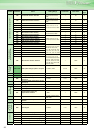
⋅ When Pr. 52 is set to "100", the set frequency monitor is displayed
during a stop and the output frequency monitor is displayed during
operation. (LED of Hz flickers during stop and is lit during
operation.)
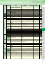
⋅ Using Pr. 867 , the output voltage response of the terminal AM can
be adjusted within the range 0 to 5s.
Set the full-scale value to output the output frequency monitor
value to terminal FM and AM.
Set the full-scale value to output the output current monitor value
to terminal FM and AM in Pr. 56.
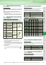
Change of DU/PU monitor descriptions Cumulative monitor clear
Pr.52
DU/PU main display data selection
Pr.54 FM terminal function selection
Pr.158 AM terminal function selection Pr.170 Cumulative power meter clear
Pr.171 Operation hour meter clear Pr.268 Monitor decimal digits selection
Pr.563 Energization time carrying-over times Pr.564 Operating time carrying-over times
Pr.867 AM output filter
Pr.891 Cumulative power monitor digit shifted times
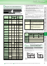
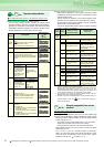
Types of Monitor
Increments
Pr.52 Parameter
Setting Value
Pr.54
(FM)
Pr.158
(AM)
Setting
Full Scale
Value
DU
LED
PU main
monitor
Output frequency
0.01Hz 0/100 1 Pr.55
Output current
0.01A/
0.1A
*6
0/100 2 Pr.56
Output voltage
0.1V 0/100 3
200V
class : 400V
400V
class : 800V
Alarm display
0/100
Frequency setting
0.01Hz 5
*1
5 Pr.55
Running speed
1(r/min) 6
*1
6
Value of Pr. 55
represented in
terms of Pr. 37
value
Converter output
voltage
0.1V 8
*1
8
200V
class : 400V
400V
class : 800V
Regenerative brake
duty
*5
0.1% 9
*1
9
Brake duty set
in Pr. 30 and
Pr. 70
Electronic thermal
relay function load
factor
0.1% 10
*1
10
Electronic
thermal relay
function
operation level
Output current peak
value
0.01A/
0.1A
*6
11
*1
11 Pr.56
Converter output
voltage peak value
0.1V 12
*1
12
200V
class : 400V
400V
class : 800V
Input power
0.01kW/
0.1kW
*6
13
*1
13
Rated inverter
power × 2
Output power
0.01kW/
0.1kW
*6
14
*1
14
Rated inverter
power × 2
Input terminal status
55
*1
Output terminal
status
*1
Option input
terminal status
56 ×
Option output
terminal status
57 ×
Load meter
0.1% 17 17 Pr.56
Reference voltage
output
21
Cumulative
energization time
*2
1h 20
Actual operation
time
*2, 3
1h 23
Motor load factor
0.1% 24 24 200%
Cumulative power
0.01kWh/
0.1kWh
*4, *6
25
Power saving effect
Variable
according
to
parameters
50 50
Inverter
capacity
Cumulative saving
power
51
PID set point
0.1% 52 52 100%
PID measured value
0.1% 53 53 100%
PID deviation value
0.1% 54
Pr.
52, 54, 158, 170, 171, 268, 563, 564, 867, 891
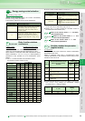
Pr. 268 Setting Description
9999 (initial value) No function
0
When 1 or 2 decimal places (0.1 increments or 0.01
increments) are monitored, the decimal places are
dropped and the monitor displays an integer value (1
increments).
The monitor value of 0.99 or less is displayed as 0.
1
When 2 decimal places (0.01 increments) are
monitored, the 0.01 decimal place is dropped and the
monitor displays the first decimal place (0.1
increments).
When the monitor display digit is originally in 1
increments, it is displayed unchanged in 1
increments.
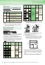
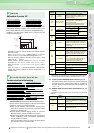
Pr.52
0 100
During
operation/stop
During stop
During
running
Output
frequency
Output frequency Set frequency Output frequency
Output
current
Output current
Output
voltage
Output voltage
Alarm
display
Alarm display
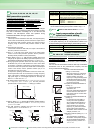
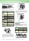
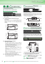
Change of the monitor output
from terminal FM and AM
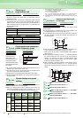
Pr.55 Frequency monitoring reference Pr.56 Current monitoring reference
Pr.
55, 56
500A
2400
pulse/s
1440
pulse/s
Output frequency
reference
Output current
reference
400Hz
Pr.56
Pulse speed(terminal FM)
Pr.55
10VDC
Output voltage(terminal AM)
400Hz
500A
Pr.56
Pr.55