29
indicates simple mode parameters and indicates extended parameters. When setting parameters, refer to the instruction manual (applied) and understand instructions.
Pr.
Pr.
Set the current of the electronic overcurrent protection to protect
the motor from overheat.This feature provides the optimum
protective characteristics, including reduced motor cooling
capability, at low speed.
This function detects the overload (overheat) of the motor, stops
the operation of the inverter's output transistor, and stops the
output.
Set the rated current [A] of the motor in Pr.9.
When using a motor with an external thermal relay, etc., set “0” in
Pr. 9 to make the electronic thermal relay function invalid. (Note
that the output transistor protection of the inverter (E.THT)
functions.)
When using the Mitsubishi constant-torque motor
1)Set “1” in Pr.71 .
(This provides a 100% continuous torque characteristic in the
low-speed range.)
2)Set the rated motor current in Pr. 9.
When the RT signal is on, thermal protection is provided based on
the Pr. 51 setting.
Use this function when rotating two motors of different rated
currents individually by a single inverter.
(When rotating two motors
together, use external thermal relays.)
The DC injection brake can be operated at a motor stop to adjust
the stop timing and braking torque.
You can set the starting frequency and hold the set starting
frequency for a certain period of time.
Set these functions when you need the starting torque or want
smooth motor drive at a start.
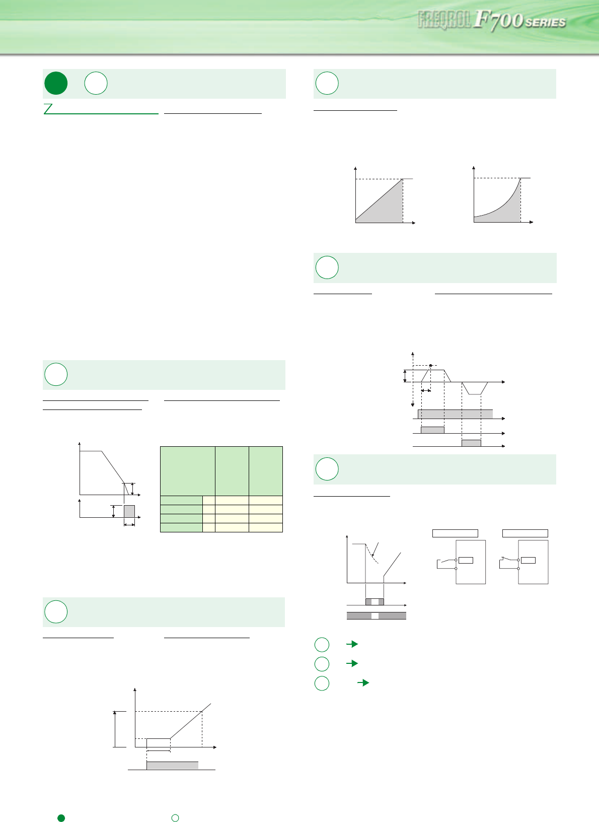
You can select the optimum output characteristic (V/F
characteristic) for the application and load characteristics.
You can set the frequency and acceleration/decelertion time for
jog operation. Jog operation can be performed from either the
outside or PU.
Can be used for conveyor positioning, test operation, etc.
The inverter output can be shut off by the MRS signal. The logic
of the MRS signal can also be selected.
Motor protection from overheat
(electronic thermal relay function)
Pr.51 Second electronic thermal O/L relay
DC injection brake
Pr.10 DC injection brake operation frequency
Pr.11 DC injection brake operation time
Pr.12 DC injection brake operation voltage
* If the Pr. 71 initial value is changed
to the setting for use with a
constant-torque motor, the Pr. 12
setting changes to the
corresponding value in the above
table.
Starting frequency
Pr.13 Starting frequency Pr.571 Holding time at a start
Pr.
9
Pr.
51
Pr.9 Electronic thermal O/L relay
Pr.
10 to 12
Time
Pr.10 Operation
frequency
Time
Pr.12
Operation
voltage
voltage
Pr.11 Operation time
Output frequency (Hz)
DC injection
brake
Pr.12 Initial
Value
When
Using the
Mitsubish
Constant
Torque
Motor
When
Using
the
Energy
Saving
Motor
3.7K or less
4%
← ←
5.5K to 7.5K 4% 2% * 3%
11K or more
2%
← ←
75K or more
1%
← ←
Pr.
13, 571
Output
frequency
(Hz)
Time
Pr.13
Pr.571 setting time
Forward
rotation ON
0
60
Setting range
V/F pattern matching applications
Pr. 14 Load pattern selection
Setting “0”
For constant-torque load
Setting “1” (initial value)
For variable-torque load
Jog operation
Pr.15 Jog frequency Pr.16 Jog acceleration/deceleration time
Logic selection of output stop
signal (MRS)
Pr.17 MRS input selection
18
Refer to the section about Pr.1, Pr.2
19
Refer to the section about Pr. 3.
20, 21
Refer to the section about Pr.7, Pr.8
Pr.
14
100%
Output voltage
Pr.3 Base frequency
Output frequency (Hz)
100%
Output voltage
Pr.3 Base frequenc
Output frequency (Hz)
Pr.
15, 16
Output
frequency
(Hz)
Pr.20
Pr.15
Jog frequency
setting range
Pr.16
Forward
rotation
Reverse
rotation
Time
ON
ON
ON
JOG signal
Forward
rotation STF
Reverse
rotation STR
Pr.
17
ON
ON
MRS signal
STF (STR)
signal
Motor coasts
to stop
Time
(Initial
value)
Output
stop
Output
stop
MRS
SD (PC)
Inverter
MRS
SD (PC)
Inverter
Setting value "0"
Setting value "2"
Pr.
Pr.
Pr.


