


Features
Standard
Specifications
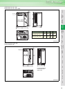
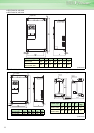
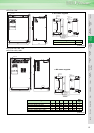
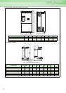
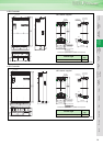
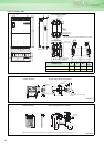
Outline
Dimension
Drawings
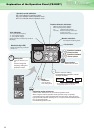
Operation
Panel
Protective
Functions
OptionsInstructionsMotorCompatibilityWarrantyInquiry
Peripheral Devices
Why energy
savings?
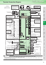
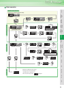
Terminal Connection
Diagram
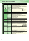
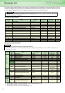
Terminal Specification
Explanation
Parameter
List
Explanations
of
Parameters
18
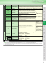
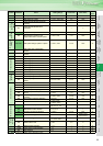
Control circuitoutput signal
Relay
A1, B1, C1
Relay output 1 (alarm
output)
Changeover contact output indicates that the inverter protective function has activated and the
output stopped. Abnormal: No conduction across B-C (Across A-C Continuity), Normal: Across
B-C Continuity (No conduction across A-C) Contact capacity: 230VAC 0.3A (Power factor=0.4)
30VDC 0.3A
A2, B2, C2 Relay output 2 1 changeover contact output Contact capacity: 230VAC 0.3A (Power factor=0.4) 30VDC 0.3A
Open collector
RUN Inverter running
Switched low when the inverter output frequency is equal to or
higher than the starting frequency (initial value 0.5Hz). Switched
high during stop or DC injection brake operation.
*1
Permissible load 24VDC
0.1A
(a voltage drop is 3.4V
maximum when the signal
is on)
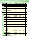
Alarm code (4bit) output
(Refer to page 36)
SU Up to frequency
Switched low when the output frequency reaches within the range
of ±10% (initial value) of the set frequency. Switched high during
acceleration/deceleration and at a stop.
*1
OL Overload alarm
Switched low when stall prevention is activated by the stall
prevention function. Switched high when stall prevention is
cancelled.
*1
IPF
Instantaneous power
failure
Switched low when an instantaneous power failure and under
voltage protections are activated.
*1
FU Frequency detection
Switched low when the inverter output frequency is equal to or
higher than the preset detected frequency and high when less than
the preset detected frequency.
*1
SE
Open collector output
common
Common terminal for terminals RUN, SU, OL, IPF, FU
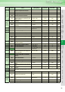
Pulse
FM For meter
Select one e.g. output frequency from monitor items. *2
The output signal is proportional to the magnitude of the
corresponding monitoring item.
Output item:
Output frequency (initial
setting)
Permissible load current
2mA
1440 pulses/s at 60Hz
Analog
AM Analog signal output
Output item:
Output frequency (initial
setting)
Output signal 0 to 10VDC
Permissible load current
1mA (load impedance
10kΩ or more) Resolution
8 bit
Communication
PU connector PU connector
With the PU connector, communication can be made through RS-485.
(for connection on a 1:1 basis only)
. Conforming standard : EIA-485(RS-485)
. Transmission format : Multidrop
. Communication speed : 4800 to 38400bps
. Overall length : 500m
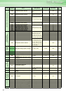
RS-485
terminal
TXD+
Inverter transmission
terminal
With the RS-485 terminal, communication can be made through RS-485.
Conforming standard : EIA-485 (RS-485)
Transmission format : Multidrop link
Communication speed : 300 to 38400bps
Overall length : 500m
TXD-
RXD+
Inverter reception
terminal
RXD-
SG Earth (Ground)
CAUTION
⋅
The inverter will be damaged if power is applied to the inverter output terminals (U, V, W). Never perform such wiring.
⋅ indicates that terminal functions can be selected fromPr. 178 to Pr. 196 (I/O terminal function selection)
*1. Low indicates that the open collector output transistor is on (conducts). High indicates that the transistor is off (does not conduct).
*2. Not output during inverter reset.
Type Terminal Symbol Terminal Name Description