


Features
Standard
Specifications
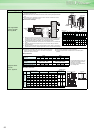
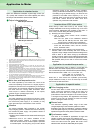
Outline
Dimension
Drawings
Operation
Panel
Protective
Functions
OptionsInstructionsMotorCompatibilityWarrantyInquiry
Peripheral Devices
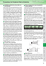
Why energy
savings?
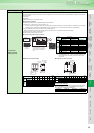
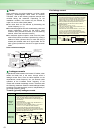
Terminal Connection
Diagram
Terminal Specification
Explanation
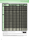
Parameter
List
Explanations
of
Parameters
64
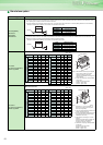
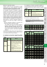
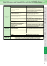
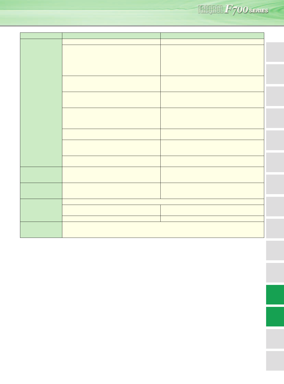
Item FR-F500 (L) FR-F700
Changed/cleared
functions
Simple mode parameters 61 Simple mode parameters 15
Pr. 0 Torque boost initial value
11K to 55K: 2%
Pr. 0 Torque boost initial value
11K to 37K: 2%, 45K, 55K: 1.5%
(When the torque boost value of the FR-F500 series
used was the initial value, it is not necessary to change
the torque boost value from the initial value when
replacing with the FR-F700 series.)
User group 1 (16), user group 2 (16)
(Pr. 160, Pr. 173 to Pr. 175)
User group (16) only
Setting methods were partially changed
(Pr. 160, Pr. 172 to Pr. 173)
User initial value setting (Pr. 199)
"User initial value setting" (Pr. 199) was cleared
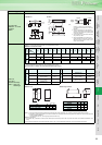
Substitutable with the copy function of the operation
panel (FR-DU07)
DC injection brake function with terminal (X13 signal)
(Pr. 11 setting value 8888, Pr. 180 to Pr. 186 setting
value 13)
DC injection brake function with terminal was cleared
Start in reverse rotation is possible with flying start
function (frequency search of automatic restart after
instantaneous power failure function)
Long wiring mode
(Pr. 240 setting 10, 11)
Setting is not necessary
(Pr. 240 settings "10" and "11" were cleared)
Intelligent optimum acceleration/deceleration
(Pr. 60 setting "3" and Pr. 61 to Pr. 63)
Function was cleared
For deceleration time, overvoltage alarm can be avoided
with regeneration avoidance function (Pr. 882 to Pr. 885).
Automatic torque boost
(Pr. 38, Pr. 39)
Automatic torque boost was cleared because of addition
of "Simple magnetic flux vector" (Pr. 80)
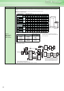
Terminal block Removable terminal block
Removable terminal block
Priority compatibility (Terminal block of the F500 can be
mounted)
PU FR-PU04, DU04
FR-DU07
FR-DU04 unavailable (Partly restricted when the FR-
PU04 is used.)
Plug-in option
Dedicated plug-in option (not compatible)
Computer link, relay output option
FR-A5NR
Built into the inverter
(RS-485 terminals, relay output 2 points)
Three boards can be mounted One board can be mounted
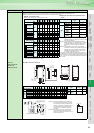
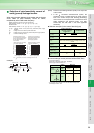
Installation size
FR-F720-0.75K, 2.2K, 3.7K, 7.5K, 18.5K, 22K, 37K, 45K,
FR-F740-0.75K to 3.7K, 7.5K, 22K, 37K to 55K are compatible in mounting dimensions
For other capacities, an optional intercompatibility attachment (FR-AAT) is necessary.
Main Differences and Compatibilities with the FR-F500(L) Series