


55
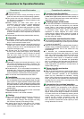
Power regeneration
common converter
FR-CV-(H)K
Enables 100%-torque continuous regeneration to support continuous regenerative
operation for line control, etc.
Eliminates the need to use a brake unit with each inverter, reducing total space and total
cost.
Saves energy since regeneration energy is used for the other inverters and excess
energy is returned to the power supply.
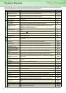
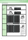
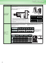
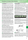
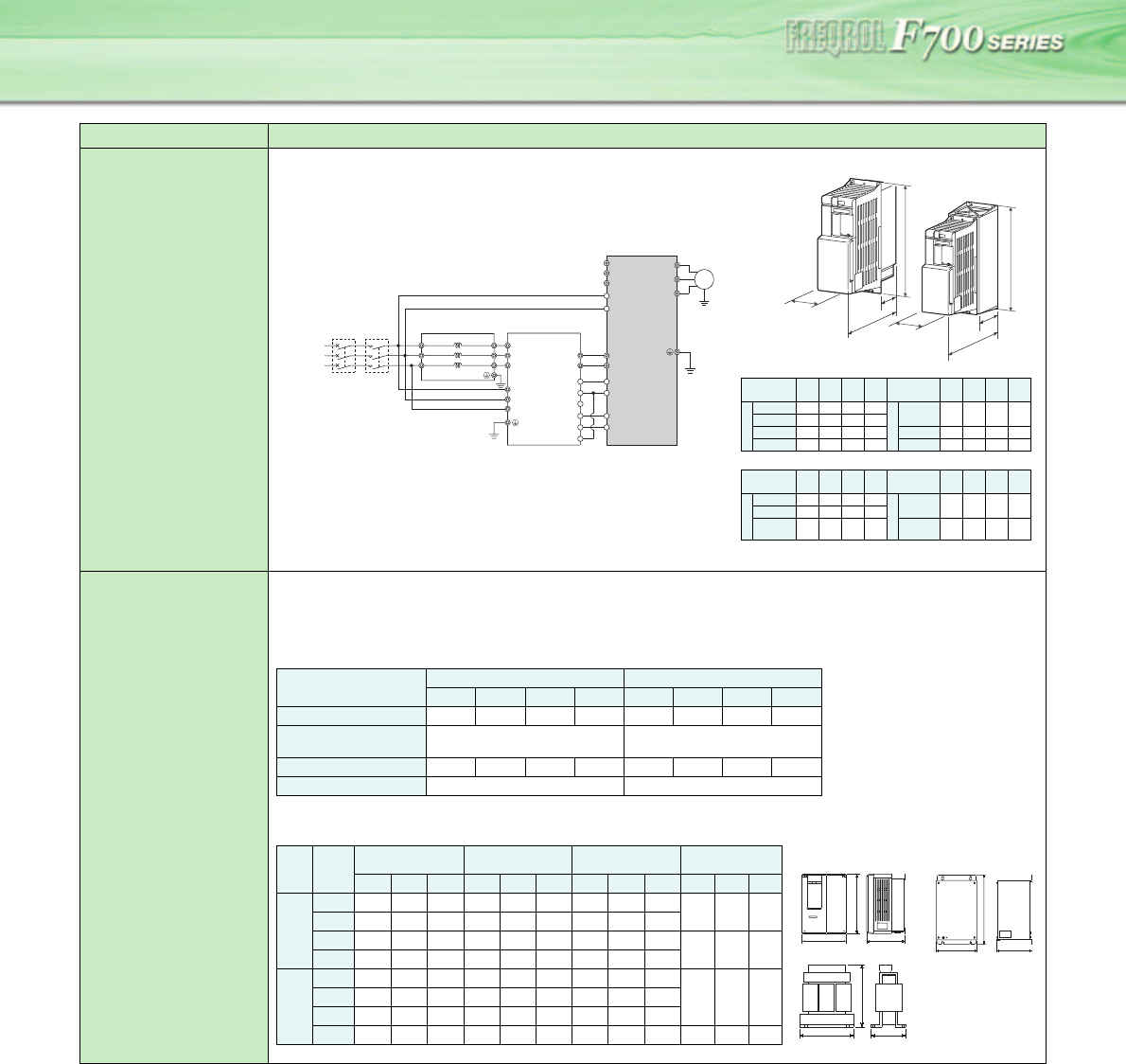
Connection example
*1. Remove the jumpers across terminals R/L1-R1/L11 and S/L2-S1/L21 of the inverter, and
connect the control circuit power supply across terminals R1/L11-S1/L21. Always keep
the power input terminals R/L1, S/L2, T/L3 open. Incorrect connection will damage the
inverter. Opposite polarity of terminals N/-, P/+ will damage the inverter.
*2. Do not insert an NFB between the terminals P/+-N/- (between P/L+-P/+, between N/
L--N/-).
*3. Assign the terminal for X10 signal using any of Pr. 178 to Pr. 189 (input terminal
function selection).
*4. Be sure to connect the power supply and terminals R/L11, S/L21, T/MC1. If the inverter is
operated without connection, the power regeneration common converter will be damaged.
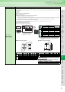
High power factor
converter
FR-HC- (H)K
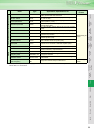
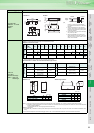
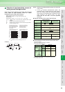
Specifications
Outline dimension
Name (type) Specifications, Structure, etc.
H
W
D1
D
H
W
D1
D
FR-CV-(H)
FR-CV-(H)-AT
FR-CV-(H) (Unit mm)
FR-CV-(H)-AT (Unit mm)
Voltage/
Capacity
W D D1 H
Voltage/
Capacity
W D D1 H
2
0
0
V
7.5K/11K
90 303 103 300
4
0
0
V
7.5K/
11K/15K
120 305 105 300
15K
120 305 105 300
22K/30K
150 322 122 380
22K/30K
150 305 105 380
37K/55K
400 250 135 620
37K/55K
400 250 135 620
Voltage/
Capacity
W D D1 H
Voltage/
Capacity
W D D1 H
2
0
0
V
7.5K/11K
110 315 115 330 4
0
0
V
7.5K/
11K/15K
130 320 120 330
15K
130 320 120 330
22K/30K
160 350 150 410
22K/30K
160 350 150 410
R/L11
Dedicated stand-alone
reactor (FR-CVL)
S/L21
T/L31
R2/L12
S2/L22
T2/L32
R2/L1
S2/L2
T2/L3
R/L11
S/L21
T/MC1
P/L+
U
V
W
IM
FR-CV type
Power regeneration
common converter
Inverter
PC
SD
X10 *3
RES
P24
SD
RDYB
RSO
SE
RDYA
N/L−
*2
*4
R/L1
S/L2
T/L3
R1/L11
S1/L21
P/+
N/−
*1
Three-phase
AC power
supply
MCCB
MC1
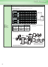
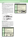
Substantially suppresses power harmonics to realize the equivalent
capacity conversion coefficient K5=0 in the "Harmonic suppression
guideline for specific consumers".
Has the power regeneration function as standard.
Connects multiple inverters to enable common converter system
operation.
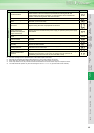
Inverter Type
FR-HC
200V 400V
*1. The applicable capacity to the high
power factor converter is the total
capacity of the inverters.
*2. The output voltage varies with the
input voltage value.
7.5K 15K 30K 55K H7.5K H15K H30K H55K
Applied inverter capacity (*1)
3.7K to 7.5K 7.5K to 15K 15K to 30K 30K to 55K 3.7K to 7.5K 7.5K to 15K 15K to 30K 30K to 55K
Rated input voltage/
frequency
Three phase 200V to 220V 50Hz
200V to 230V 60Hz
Three phase
380V to 460V 50/60Hz
Rated input current (A) 33 61 115 215 17 31 57 110
Rated output voltage (V) (*2)
293VDC to 335VDC 558VDC to 670VDC
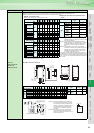
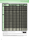
(Unit: mm)
Voltage Capacity
High Power Factor
Converter FR-HC
Reactor 1 FR-HCL01 Reactor 2 FR-HCL02
Outside Box FR-
HCB
W H D W H D W H D W H D
2
0
0
V
7.5K 220 300 190 160 155 100 240 230 160
190 320 165
15K 250 400 190 190 205 130 260 270 170
30K 340 550 195 220 230 170 340 320 180
270 450 203
55K 480 700 250 210 260 225 430 470 360
4
0
0
V
H7.5K 220 300 190 160 150 100 240 220 160
190 320 165H15K 250 400 190 190 195 130 260 260 170
H30K 340 550 195 220 215 140 340 310 180
H55K 480 700 250 280 255 190 400 380 285 270 450 203
D
W
H
High power factor converter
W
D
H
Reactor 1, Reactor 2
H
W
D
Outside box