


Features
Standard
Specifications
Outline
Dimension
Drawings
Operation
Panel
Protective
Functions
OptionsInstructionsMotorCompatibilityWarrantyInquiry
Peripheral Devices
Why energy
savings?
Terminal Connection
Diagram
Terminal Specification
Explanation
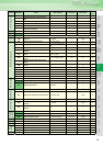
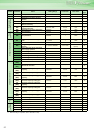
Parameter
List
Explanations
of
Parameters
30
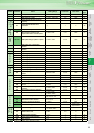
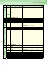
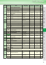
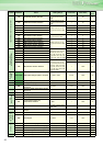
indicates simple mode parameters and indicates extended parameters. When setting parameters, refer to the instruction manual (applied) and understand instructions.
Pr.
Pr.
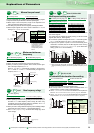
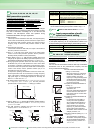
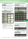
This function monitors the output current and automatically changes
the output frequency to prevent the inverter from coming to an alarm
stop due to overcurrent, overvoltage, etc. It can also limit stall
prevention and fast-response current limit operation during
acceleration/deceleration, driving or regeneration.
Stall prevention
If the output current exceeds the limit value, the output frequency
of the inverter is automatically varied to reduce the output current.
Also the second stall prevention function can restrict the output
frequency range in which the stall prevention function is valid.
(Pr.49)
Fast-response current limit
If the current exceeds the limit value, the output of the inverter is
shut off to prevent an overcurrent.
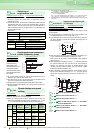
Set in Pr. 22 the ratio of the output current to the rated inverter
current at which stall prevention operation will be performed.
Normally set this parameter to120% (initial value).
When “9999” is set in Pr. 22, stall prevention operation level can be
changed by the signal to the auxiliary input terminal (terminal 1). For
the adjustment of bias/gain of analog signal, use Pr. 148 and Pr. 149.
During high-speed operation above the rated motor frequency,
acceleration may not be made because the motor current does
not increase. If operation is performed in a high frequency range,
the current at motor lockup becomes smaller than the rated output
current of the inverter, and the protective function (OL) is not
executed if the motor is at a stop.
To improve the operating characteristics of the motor in this case,
the stall prevention level can be reduced in the high frequency
region. This function is effective for performing operation up to the
high speed region on a centrifugal separator etc. Normally, set
60Hz in Pr. 66 and 100% in Pr. 23.
By setting "9999" (initial value) in Pr. 23 Stall prevention operation
level compensation factor at double speed, the stall prevention
operation level is constant at the Pr. 22 setting up to 400Hz.
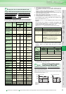
Setting "9999" in Pr. 49 Second stall prevention operation frequency
and turning the RT signal on make Pr. 48 Second stall prevention
operation current valid.
The stall prevention operation level from 0Hz to the output
frequency set in Pr. 49 can be set in Pr. 48.
Stall prevention operation and fast response current restriction function
can be restricted according to the operation condition using Pr. 156.
By inputting the frequency setting compensation signal (terminal 1,
2), the speed (frequency) can be compensated for relative to the
multi-speed setting or the speed setting by remote setting function.
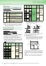
You can set the acceleration/deceleration pattern suitable for
application.
You can also set the backlash measures that stop acceleration/
deceleration once at the parameter-set frequency and time
during acceleration/deceleration.
Stall prevention operation
Pr.22 Stall prevention operation level
Pr.23 Stall prevention operation level compensation factor at double speed
Pr.48 Second stall prevention operation current Pr.49 Second stall prevention operation frequency
Pr.66 Stall prevention operation reduction starting frequency
Pr.148 Stall prevention level at 0V input.
Pr.149 Stall prevention level at 10V input.
Pr.154 Voltage reduction selection during stall prevention operation
Pr.156 Stall prevention operation selection
Pr.157 OL signal output timer
Pr.
22, 23, 48, 49, 66, 148, 149, 154, 156, 157
Output frequency (Hz
)
P
r. 22
Pr.23
When Pr.23=9999
Pr.66
400Hz
Stall prevention operation
level (%)
Reduction ratio compensation
factor (%)
Pr. 22
used
Pr.49
Pr. 48
used
Output
frequency (Hz)
Output
frequency
Set
frequency
Set frequency is Pr. 49 or less
Tim
e
Pr. 22
used
Pr.49
Output
frequency (Hz)
Output
frequency
Stall
prevention
level
Set frequency exceeds Pr. 49
Pr. 48
used
Set
frequency
Time
Pr. 49 Setting Operation
0 (initial value) Second stall prevention function is not activated
0.01Hz to 400Hz
If the output frequency is less than the frequency set in
Pr. 49, the second stall prevention operation function is
activated. (during constant speed or deceleration)
9999
The second stall prevention function is performed according to
the RT signal.
RT signal on .......Stall level Pr. 48
RT signal off .......Stall level Pr. 22
24 to 27
Refer to the section about Pr.4 to Pr.6
Input compensation of multi-
speed and remote setting
Pr.28 Multi-speed input compensation selection
Pr. 28 Setting Definition
0 (initial value) Without compensation
1 With compensation
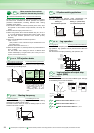
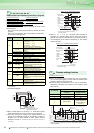
Acceleration/ deceleration pattern
and back lash measures
Pr.29 Acceleration/deceleration pattern selection Pr.140 Backlash acceleration stopping frequency
Pr.141 Backlash acceleration stopping time Pr.142 Backlash deceleration stopping frequency
Pr.143 Backlash deceleration stopping time
Linear acceleration/deceleration
(setting "0", initial value)
⋅ When the frequency is changed for
acceleration, deceleration, etc. in
inverter operation, the output
frequency is changed linearly (linear
acceleration/deceleration) to reach
the set frequency without straining
the motor and inverter.
S-pattern acceleration/deceleration A
(setting "1")
⋅ For machine tool spindle
applications, etc.
Use when acceleration/deceleration
must be made in a short time to a
high-speed region of not lower than
base frequency.
S-pattern acceleration/deceleration B
(setting "2")
⋅ For prevention of load shifting in
conveyor and other applications
Since acceleration/deceleration is
always made in an S shape from
current frequency (f2) to target
frequency (f1), this function eases
shock produced at acceleration/
deceleration and is effective for load
collapse prevention, etc.
Backlash measures (setting "3", Pr.140
to Pr.143 )
⋅ To avoid backlash, acceleration/
deceleration is temporarily stopped.
Set the acceleration/deceleration
stopping frequency and time in Pr.
140 to Pr. 143.
Pr.
Pr.
28
Pr.
29, 140 to 143
Setting value "0"
[Linear acceleration
/ deceleration]
Output frequency
(Hz)
Time
fb
Output frequency
(Hz)
Setting value "1"
Time
[S-pattern acceleration
/deceleration A]
f1
Setting value "2"
[S-pattern acceleration
/deceleration B]
f2
Time
Set frequency
(Hz)
Output frequency
(Hz)
[Anti-backlash measure
function]
f2
Pr.142
Pr.143
Pr.141
Pr.140
Time
Output frequency (Hz)
Setting value "3"
t1
t2
f1