


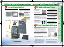
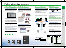

Features
Standard
Specifications
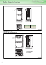
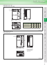
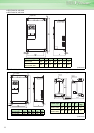
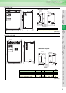
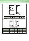
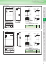
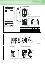
Outline
Dimension
Drawings
Operation
Panel
Protective
Functions
OptionsInstructionsMotorCompatibilityWarrantyInquiry
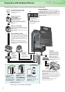
Peripheral Devices
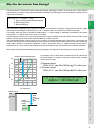
Why energy
savings?
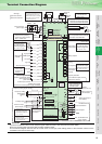
Terminal Connection
Diagram
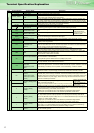
Terminal Specification
Explanation
Parameter
List
Explanations
of
Parameters
8
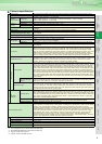
Common specifications
Control specifications
Control system High carrier frequency PWM control (V/F control)/optimum excitation control/simple magnetic flux vector control
Output frequency range 0.5 to 400Hz
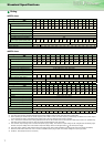
Frequency
setting resolution
Analog input
0.015Hz/0 to 60Hz (terminal 2, 4: 0 to 10V/12bit)
0.03Hz/0 to 60Hz (terminal 2, 4: 0 to 5V/11bit, 0 to 20mA/11bit, terminal 1: -10V to +10V/11bit)
0.06Hz/0 to 60Hz (terminal 1: 0 to ±5V/10bit)
Digital input 0.01Hz
Frequency
accuracy
Analog input Within ±0.2% of the max. output frequency (25°C ± 10°C)
Digital input Within 0.01% of the set output frequency
Voltage/frequency characteristics
Base frequency can be set from 0 to 400Hz Constant torque/variable torque pattern or adjustable 5 points V/F can
be selected
Starting torque 120% (3Hz) when set to simple magnetic flux vector control and slip compensation
Acceleration/deceleration time setting
0 to 3600s (acceleration and deceleration can be set individually), linear or S-pattern acceleration/deceleration mode
can be selected.
DC injection brake Operation frequency (0 to 120Hz), operation time (0 to 10s), operation voltage (0 to 30%) variable
Stall prevention operation level Operation current level can be set (0 to 150% adjustable), whether to use the function or not can be selected
Operation specifications
Frequency
setting signal
Analog input
Terminal 2, 4: 0 to 10V, 0 to 5V, 4 to 20mA can be selected
Terminal 1: -10 to +10V, -5 to 5V can be selected
Digital input Four-digit BCD or16-bit binary using the setting dial of the operation panel (when used with the option FR-A7AX)
Start signal
Available individually for forward rotation and reverse rotation. Start signal automatic self-holding input (3-wire input)
can be selected.
Input signals
You can select any twelve signals using Pr.178 to Pr.189 (input terminal function selection) from among multi speed
selection, second function selection, terminal 4 input selection, JOG operation selection, selection of automatic
restart after instantaneous power failure, external thermal relay input, HC connection (inverter operation enable
signal), HC connection (instantaneous power failure detection), PU operation/external inter lock signal , PID control
enable terminal, PU operation, external operation switchover, output stop, start self-holding selection, forward
rotation command, reverse rotation command, inverter reset, PTC thermistor input, PID forward reverse operation
switchover, PU-NET operation switchover, NET-external operation switchover, command source switchover.
Operational functions
Maximum and minimum frequency settings, frequency jump operation, external thermal relay input selection, polarity
reversible operation, automatic restart after instantaneous power failure operation, original operation continuation at
instantaneous power failure, commercial power supply-inverter switchover operation, forward/reverse rotation
prevention, operation mode selection, PID control, computer link operation (RS-485).
Output signals
Operating status
You can select any seven signals using Pr.190 to Pr.196 (output terminal function selection) from among inverter
running, up-to-speed, instantaneous power failure /undervoltage, overload warning, output frequency detection, second
output frequency detection, regenerative brake prealarm
*4, electronic thermal relay function pre-alarm, PU operation
mode, inverter operation ready, output current detection, zero current detection, PID lower limit, PID upper limit, PID
forward rotation reverse rotation output, commercial power supply-inverter switchover MC1, commercial power supply-
inverter switchover MC2, commercial power supply-inverter switchover MC3, fan fault output, heatsink overheat pre-
alarm, inverter running start command on, deceleration at an instantaneous power failure, PID control activated, during
retry, during PID output suspension, life alarm, alarm output 3 (power-off signal), power savings average value update
timing, current average monitor, alarm output 2, maintenance timer alarm, remote output, minor failure output, alarm
output. Open collector output (5 points), relay output (2 points) and alarm code of the inverter can be output (4 bit) from
the open collector.
When used with the
FR-A7AY, FR-A7AR
(option)
You can select any seven signals using Pr.313 to Pr. 319 (extension output terminal function selection) from among
control circuit capacitor life, main circuit capacitor life, cooling fan life, inrush current limit circuit life and the above
stated signals. (Only positive logic can be set for terminals of the FR-A7AR.)
Pulse/analog output
Selection can be made from output frequency, motor current (steady or peak value), output voltage, frequency setting
value, running speed, converter output voltage (steady or peak value), electronic thermal relay function load factor,
input power, output power, load meter, reference voltage output, motor load factor, power saving effect, regenerative
brake duty
*4, PID set value, PID measured value using Pr.54 "FM terminal function selection (pulse train output)" and
Pr.158 "AM terminal function selection (analog output)".
Display
PU
(FR-DU07/
FR-PU04)
Operating status
Output frequency, motor current (steady or peak value), output voltage, frequency setting, running speed, converter
output voltage (steady or peak value), electronic thermal relay function load factor, input power, output power, load
meter, cumulative energization time, actual operation time, motor load factor, cumulative energization power, power
saving effect, cumulative saving power, regenerative brake duty
*4, PID set point, PID measured value, PID deviation
value, inverter I/O terminal monitor, input terminal option monitor
*1, output terminal option monitor*1, option fitting
status monitor
*2, terminal assignment status*2
Alarm definition
Alarm definition is displayed when the protective function is activated, the output voltage/current/frequency/cumulative
energization time right before the protection function was activated and the past 8 alarm definitions are stored
Interactive guidance Operation guide/trouble shooting with a help function*2
Protective/warning function
Overcurrent during acceleration, overcurrent during constant speed, overcurrent during deceleration, overvoltage
during acceleration, overvoltage during constant speed, overvoltage during deceleration, inverter protection thermal
operation, motor protection thermal operation, heatsink overheat, instantaneous power failure occurrence,
undervoltage, input phase failure, motor overload, output side earth (ground) fault overcurrent, output phase failure,
external thermal relay operation, PTC thermistor operation, option alarm, parameter error, PU disconnection, retry
count excess, CPU alarm, operation panel power supply short circuit, 24VDC power output short circuit, output
current detection value excess, inrush resistance overheat, communication alarm (inverter), analog input alarm,
internal circuit alarm (15V power supply), fan fault, overcurrent stall prevention, overvoltage stall prevention,
electronic thermal relay function prealarm, PU stop, maintenance timer alarm
*1, brake transistor alarm*4, parameter
write error, copy operation error, operation panel lock, parameter copy alarm
Environment
Ambient temperature -10°C to +50°C (non-freezing)
Ambient humidity 90%RH or less (non-condensing)
Storage temperature*3 -20°C to +65°C
Atmosphere Indoors (without corrosive gas, flammable gas, oil mist, dust and dirt etc.)
Altitude, vibration
Maximum 1000m above seal level, 5.9m/s
2
or less *5 (conforms to JIS C 60068-2-6)
*1. Can be displayed only on the operation panel (FR-DU07).
*2. Can be displayed only on the parameter unit (FR-PU04).
*3. Temperature applicable for a short period in transit, etc.
*4. Only the 75K or more functions.
*5. 2.9m/s
2
or less for the 185K or more.