


43
Features
Standard
Specifications
Outline
Dimension
Drawings
Operation
Panel
Protective
Functions
OptionsInstructionsMotorCompatibilityWarrantyInquiry
Peripheral Devices
Why energy
savings?
Terminal Connection
Diagram
Terminal Specification
Explanation
Parameter
List
Explanations
of
Parameters
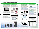
Full of attractive features!
•
I
nverter noises have been reduced with the adoption of new technologies.
¥
Because of the built-in capacitive filter and zero-phase reactor (55K or less),
connecting the optional DC reactor to the inverter will comply with the
electric installation work common specification and machine installation
work common specification (2001) written under the general editorship of
the Japanese Ministry of land, infrastructure and transportation.
¥Because of the built-in EMC filter, the inverter itself can
comply with the EMC Directive (2nd environment*
1
) by
setting the connector to "with filter"(*
2,
*
3
).
(1)
Reduction of electromagnetic noises
•
Because of the built-in inrush current limit circuit, the current
at power on is restricted.
(3)
Equipped with inrush current limit circuit
¥
AC reactor and DC reactor options for the control of
harmonics current output has been miniaturized.
(DC reactor is supplied with the 75K or more as standard.)
(2)
Countermeasures for harmonic current output
EF
•Newly developed noise filter (EMC filter)
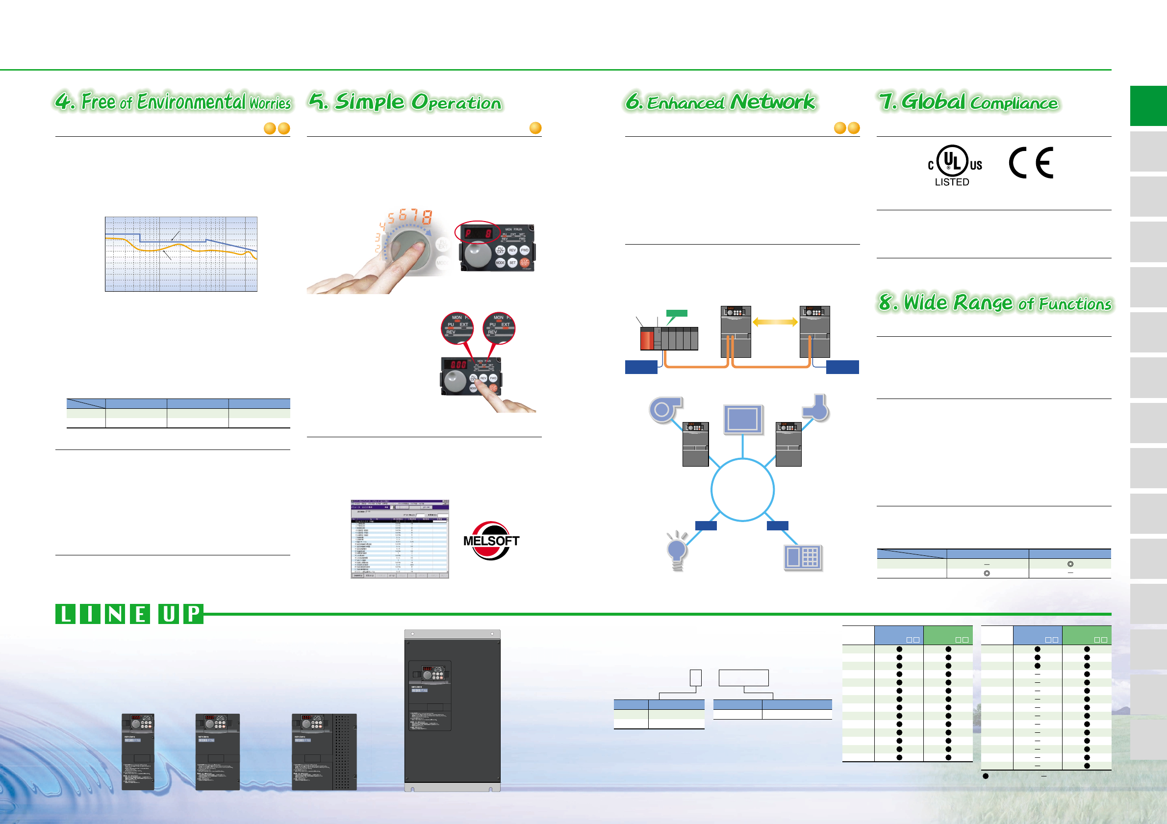
(1)
Equipped with operation panel with the popular setting dial
•
From start up to maintenance of the inverter is simple.
•
Possible to save and print parameter setting file making
parameter management simple
(Possible to use communications connecting to any of PU connector and RS-485 terminals)
(2) FR Configurator (setup software)
AGH
•Operation is easy with the popular setting dial.
¥Frequency and parameters can be set without frustrations.
¥
Settings can be made quickly or slowly depending on fast
the dial is being turned.
¥
Settings are certain due to the "clicking" sensation and notch on dial.
•RS-485 terminals are available in addition to the PU.
connector. RS-485 communication can be performed using
the operation panel or parameter unit. Since terminals for
input and output are provided separately, multi-drop
connection is easily done.
•Modbus-RTU (Binary) protocol has been added for
communications in addition to computer link.
(1)
RS-485 terminal is standard equipped
(1)
Complies with UL, cUL, EN (LVD) standards
(1) Remote output function
(2)
Possible to switch sink/source with one-touch
•Possible to connect with LONWORKS, CC-Link Ver.1.1 and Ver.2.0,
DeviceNet
TM
and Profibus-DP when used with communication
options
•You can utilize the on/off of the inverter's output signals
instead of the remote output function of the programmable
logic controller.
•
Possible to switch the logic of I/O terminals. Possible to use in
all regions
(3) Wide voltage range
•
Accommodate both 240V power supply (55K or less) and
480V power supply as standard
(2) Enhanced I/O is standard
•12 contact inputs, 3 analog inputs, 5 open collector outputs, 2
relay outputs, analog output and pulse output are all standard.
•Possible to assign variety of functions to contact inputs, open
collector outputs and relay outputs
•
Possible to switch between voltage and current for the analog input.
•Possible to display the ON/OFF status of the I/O terminals on
the operation panel
(2)
Possible to correspond with major networks
•High torque in low speed region is possible with simple
magnetic flux vector control
(120% torque is possible at 3Hz with slip compensation)
(3)
Simple magnetic flux vector control is possible
For torque
For energy savings
V/F + Optimum Excitation
Simple Magnetic Flux Vector
Voltage
200V class
400V class
Symbol
2
4
0.75
1.5
2.2
3.7
5.5
7.5
11
15
18.5
22
30
37
45
55
Inverter Capacity
Indicate capacity (kW)
Symbol
0.75K to 560K
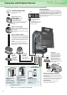
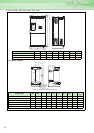
CC-Link
dedicated cable
CC-Link network
Inverter
Inverter
FR-A7NC FR-A7NC
Inverter
Master
CPU
Power
supply
unit
Terminating
resistor
Terminating
resistor
when connections
are inverter only
( )
Up to 42 units can
be connected
LONWORKS
Network
Free
Topology
Network management
computer
Pump
Air-conditioner
FR-A7NL
Inverter
FR-A7NL
Node Node
Security systemLighting
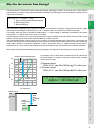
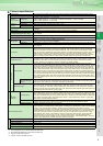
Example of parameter change
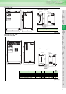
•Operation panel is detachable and can be installed on the
front cover. (Cable connector
option is required.)
•PU/EXT (operation mode)
switchover key is available.
•Dial/key operation lock
function is available.
PU/EXT
Example of
operation mode
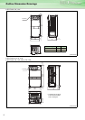
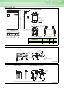
•Small AC reactor (FR-HAL)/DC reactor (FR-HEL)
¥Connection is possible to high power-factor converter for effective
suppressions of power-supply harmonics (coefficient K5=0).
•
Connection with high power factor converter (FR-HC/MT-HC) is possible
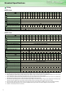
75
90
110
132
160
185
220
250
280
315
355
400
450
500
560
Applied Motor
(kW)
Applied Motor
(kW)
130
120
110
100
90
80
70
60
50
40
30
20
10
0
.15 .2 .3 .5 .7 1 2 3 5 7 10 20 30
[dBuV]
Frequency [MHz]
[FR-F740-37K Conducted noise data]
EN61800-3
second Environment QP level
QP value
L
ON
W
ORKS
®
is a registered trademark of Echelon Corporation and DeviceNet is of ODVA.
:Available models :Not available
Three-phase 200V class
FR-F720-
Three-phase 400V class
FR-F740-
Three-phase 200V class
FR-F720-
Three-phase 400V class
FR-F740-
FR-F7 2 0- 0.75K
*1:
Refer to the EMC instruction manual for compliance conditions.
*2: Leakage current will increase when the EMC filter is selected.
*3: Since the leakage current when using the EMC filter for the 200V class 0.75K and
1.5K is small, the filter is always valid (a setting connector is not provided).
55K or less
75K or more
Capacitive filter
Standard (Built-in)
Standard (Built-in)
Zero-phase reactor
Standard (Built-in)
Option (Sell separately)
DC reactor
Option (Sell separately)
Standard (supplied)