


Features
Standard
Specifications
Outline
Dimension
Drawings
Operation
Panel
Protective
Functions
OptionsInstructionsMotorCompatibilityWarrantyInquiry
Peripheral Devices
Why energy
savings?
Terminal Connection
Diagram
Terminal Specification
Explanation
Parameter
List
Explanations
of
Parameters
58
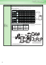
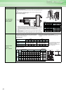
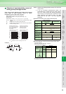
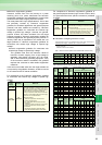
Selection of rated sensitivity current of
earth (ground) leakage breaker
When using the earth leakage circuit breaker with the inverter
circuit, select its rated sensitivity current as follows,
independently of the PWM carrier frequency:
example
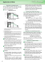
(Note)1. Install the earth leakage breaker (ELB) on the input side
of the inverter.
2. In the connection earthed-neutral system, the
sensitivity current is purified against an earth (ground)
fault in the inverter output side. Earthing (Grounding)
must conform to the requirements of national and local
safety regulations and electrical codes. (JIS, NEC
section 250, IEC 536 class 1 and other applicable
standards)
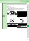
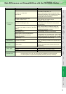
Selection example (in the case of the left figure)
Inverter leakage current (with and without EMC filter)
Input power conditions
(200V class : 220V/60Hz, 400V class : 440V/60Hz,
power supply unbalance within 3%)
* For the 200V class 0.75K and 1.5K, the EMC filter is always valid.
The leakage current is 1mA.
⋅ Breaker designed for harmonic and surge suppression
Rated sensitivity currentI ∆n ≥ 10 × (Ig1 + Ign + Igi + Ig2 + Igm)
⋅ Standard breaker
Rated sensitivity currentI ∆n ≥ 10 × {Ig1 + Ign + Igi + 3 × (Ig2 + Igm)}
Ig1, Ig2 : Leakage currents in wire path during commercial power supply
operation
Ign : Leakage current of inverter input side noise filter
Igm : Leakage current of motor during commercial power supply operation
Igi : Inverter unit leakage current
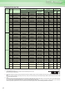
Motor capacity (kW)
For " " connection, the amount of leakage current is 1/3
(Three-phase three-wire delta
connection 400V60Hz)
Example of leakage current
per 1km during the commercial
power supply operation when
the CV cable is routed in
metal conduit
Leakage current example of
Three-phase induction moto
r
during the commercial
power supply operation
(Totally-enclosed fan-cooled
type motor 400V60Hz)
0
20
40
60
80
100
120
leakage currents (mA)
leakage currents (mA)
23.5
5.5
81422
30
38
60
80
100
150
Power supply size (mm
2
)
0. 1
0. 2
0. 3
0. 5
0. 7
1. 0
2. 0
1. 5 3. 7
2. 2
7. 5 1522
11
37
30
55
455.5 18. 5
Noise
filter
Inverter
ELB
Ig1 Ign
Igi
Ig2 Igm
5.5mm
2
×
5m 5.5mm
2
×
60m
IM
3φ
400V
2.2k
W
Voltage
(V)
EMC Filter
ON (mA) OFF (mA)
200 22(1) * 1
400 30 1
400 1 1
Breaker Designed for
Harmonic and Surge
Suppression
Standard Breaker
Leakage current
Ig1 (mA)
1
× 66 ×
5m
= 0.11
3 1000m
Leakage current
Ign (mA)
0 (without noise filter)
Leakage current Igi
(mA)
1 (Without EMC filter)
Refer to the following table for the leakage current of the
inverter
Leakage current
Ig2(mA)
1
× 66 ×
60m
= 1.32
3 1000m
Motor leakage
current Igm (mA)
0.36
Total leakage
current (mA)
2.79 6.15
Rated sensitivity
current (mA)(≥ Ig ×
10)
30 100
Phase
grounding
Earthed-neutral
system