


61
Noise
When performing low-noise operation at higher carrier
frequency, electromagnetic noise tends to increase.
Therefore, refer to the following measure example and
consider taking the measures. Depending on the
installation condition, the inverter may be affected by
noise in a non-low noise (initial) status.
The noise level can be reduced by decreasing the
carrier frequency (Pr. 72).
As measures against AM radio broadcasting noise and
sensor malfunction, turning on the built-in noise
reduction filter produces an effect. (For the switching
method, refer to the instruction manual.)
As measures against induction noise from the power
cable of the inverter, an effect is produced by putting a
distance of 30cm (at least 10cm) or more and using a
twisted pair shielded cable as a signal cable. Do not
earth (ground) shield but connect it to signal common
cable.
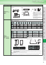
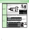
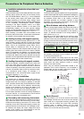
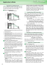
Noise reduction examples
Leakage currents
Capacitances exist between the inverter I/O cables, other
cables and earth and in the motor, through which a
leakage current flows. Since its value depends on the
capacitances, carrier frequency, etc., low acoustic noise
operation at the increased carrier frequency of the
inverter will increase the leakage current. Therefore, take
the following measures. Select the earth leakage breaker
according to its rated sensitivity current, independently of
the carrier frequency setting.
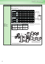
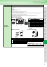
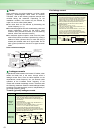
To-earth (ground) leakage currents
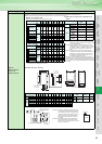
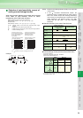
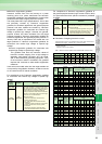
Line leakage current
Type Influence and Measures
Influence
and
measures
⋅ Leakage currents may flow not only into the inverter's own
line but also into the other lines through the earth (ground)
cable, etc.These leakage currents may operate earth
(ground) leakage circuit breakers and earth leakage relays
unnecessarily.
Countermeasures
⋅ If the carrier frequency setting is high, decrease the Pr. 72
PWM frequency selection setting.
Note that motor noise increases. Select Pr. 240 Soft-PWM
operation selection to make the sound inoffensive.
⋅ By using earth leakage circuit breakers designed for
harmonic and surge suppression in the inverter's own line
and other line, operation can be performed with the carrier
frequency kept high (with low noise).
Undesirable
current path
Inverter
Sensor
Use a twisted pair shielded cable
Enclosure Decrease carrier frequency
Motor
IM
FR-
BLF
Do not earth (ground) control cable.
Inverter
power
supply
Install filter (FR-BLF,
FR-BSF01) on
inverter output side.
Separate inverter and
power line by more than
30cm (at least 10cm)
from sensor circuit.
Control
power
supply
Do not earth (ground)
enclosure directly.
Power
supply for
sensor
Use 4-core cable for motor
power cable and use one cable
as earth (ground) cable.
Do not earth (ground) shield but
connect it to signal common cable.
EMC
filter
Power
supply
Leakage
breaker
Leakage
breaker
NV1
NV2
Inverter
Motor
Motor
C
C
C
Type Influence and Measures
Influence
and
measures
⋅ This leakage current flows via a static capacitance between
the inverter output cables.
⋅ The external thermal relay may be operated unnecessarily
by the harmonics of the leakage current.When the wiring
length is long (50m or more) for the 400V class small-
capacity model (7.5kW or less), the external thermal relay is
likely to operate unnecessarily because the ratio of the
leakage current to the rated motor current increases.
Countermeasures
⋅ Use Pr. 9 Electronic thermal O/L relay.
⋅ If the carrier frequency setting is high, decrease the Pr. 72
PWM frequency selection setting.
Note that motor noise increases. Select Pr. 240 Soft-PWM
operation selection to make the sound inoffensive.
To ensure that the motor is protected against line-to-line
leakage currents, it is recommended to use a temperature
sensor to directly detect motor temperature.
Undesirable
current path
Power
supply
Thermal relay
line-to-line static
capacitances
MCCB MC
Line-to-line leakage currents path
Motor
Inverter
IM