


Features
Standard
Specifications
Outline
Dimension
Drawings
Operation
Panel
Protective
Functions
OptionsInstructionsMotorCompatibilityWarrantyInquiry
Peripheral Devices
Why energy
savings?
Terminal Connection
Diagram
Terminal Specification
Explanation
Parameter
List
Explanations
of
Parameters
38
indicates simple mode parameters and indicates extended parameters. When setting parameters, refer to the instruction manual (applied) and understand instructions.
Pr.
Pr.
.
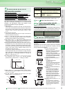
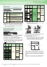
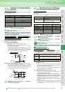
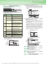
A dedicated V/F pattern can be made by freely setting the V/F
characteristic between a startup and the base frequency and
base voltage under V/F control (frequency voltage/frequency).
Possible to set the torque pattern that is optimum for the
machine’s characteristic
⋅ Adjustable 5 points V/F will not function under simple magnetic
flux vector control.
⋅ When Pr. 19 Base frequency voltage = "8888" or "9999", Pr. 71 cannot be
set to "2". To set Pr. 71 to "2", set the rated voltage value to Pr. 19
⋅ When the frequency values of the points are the same, a write
inhibit error ( ) occurs.
⋅ Set the points (frequencies, voltages) of Pr. 100 to Pr. 109 within
the ranges of Pr. 3 Base frequency and Pr. 19 Base frequency voltage .
⋅ When “2” is set in Pr. 71, Pr. 47 Second V/F (base frequency) will not
function.
⋅ When “2” is set in Pr. 71, thermal characteristic of the electronic
thermal relay function changes to thermal characteristics of a
standard motor.
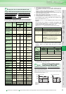
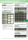
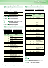
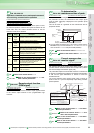
(1) Initial settings and specifications of RS-485
communication (Pr.117 to Pr.124, Pr.331 to Pr.337, Pr.341)
Used to perform required settings for RS-485 communication
between the inverter and personal computer.
There are two different communications: communication
using the PU connector of the inverter and communication
using the RS-485 terminals.
You can perform parameter setting, monitor, etc. using the
Mitsubishi inverter protocol or Modbus-RTU protocol.
To make communication between the personal computer and
inverter, initialization of the communication specifications
must be made to the inverter.
Data communication cannot be made if the initial settings
are not made or there is any setting error.
*1 When making communication through Modbus-RTU protocol with the RS-
485 terminals, the setting range of Pr. 331 within parenthesis is applied.
*2 The values in parenthesis are added to the setting range of Pr. 332.
(2) Communication EEPROM write selection (Pr.342)
Parameters written via the inverter's PU connector or RS-485
terminals or from the communication option can be written to
the RAM. When performing parameter change frequently, set
"1" in Pr. 342.
(3) Modbus-RTU communication specifications (Pr.343,
Pr.549)
* The Modbus-RTU protocol is valid for only communication from the RS-485
terminals.
Adjustable 5 points V/F
Pr.100 V/F1 (first frequency)
Pr.101 V/F1 (first frequency voltage)
Pr.102 V/F2 (second frequency)
Pr.103 V/F2 (second frequency voltage)
Pr.104 V/F3 (third frequency)
Pr.105 V/F3 (third frequency voltage)
Pr.106 V/F4 (fourth frequency)
Pr.107 V/F4 (fourth frequency voltage)
Pr.108 V/F5 (fifth frequency)
Pr.109 V/F5 (fifth frequency voltage)
Communication initial setting
Pr.117 PU communication station Pr.118 PU communication speed
Pr.119
PU communication stop bit length.
Pr.120 PU communication parity check
Pr.121
Number of PU communication retries
Pr.122 PU communication check time interval
Pr.123 PU communication waiting time setting
Pr.124 PU communication CR/LF presence/absence selection
Pr.331 RS-485 communication station Pr.332 RS-485 communication speed
Pr.333
RS-485 communication stop bit length
Pr.334 RS-485 communication parity check selection
Pr.335 RS-485 communication number of retries Pr.336 RS-485 communication check time interval
Pr.337 RS-485 communication waiting time setting
Pr.341 RS-485 communication CR/LF selection Pr.342 Communication EEPROM write selection
Pr.343 Communication error count Pr.549 Protocol selection
Pr.
100 to 109
B
ase frequency
voltage
Pr.19
Base frequency
Pr.3
Torque boost
Pr.0
V/F Characteristic
0
V/F5
V/F4
V/F3
V/F2
V/F1
Frequency
Voltage
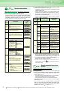
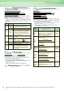
Pr.
117 to 124, 331 to 337, 341 to 343, 549
Pr.
Number
Setting Range Description
117
331
0 to 31
(0 to 247)
*1
Specify the inverter station number.
Set the inverter station numbers when two
or more inverters are connected to one
personal computer.
118
332
48, 96, 192, 384
(3, 6, 12, 24)
*2
Set the communication speed.
The setting value × 100 equals the
communication speed.
For example, the communication speed is
19200bps when the setting value is "192".
119
333
Stop bit length Data length
0 1bit
8bit
1 (initial value) 2bit
10 1bit
7bit
11 2bit
120
334
0 Without parity check
1 With odd parity check
2 (initial value) With even parity check
121
335
0 to 10
Set the permissible number of retries at
occurrence of a data receive error. If the
number of consecutive errors exceeds the
permissible value, the inverter will come to
an alarm stop.
9999
If a communication error occurs, the
inverter will not come to an alarm stop.
122
336
0
No PU connector communication
Communication with RS-485 terminal can
be made, but the inverter will come to an
alarm stop in the NET operation mode.
0.1 to 999.8s
Set the interval of communication check
time.
If a no-communication state persists for
longer than the permissible time, the
inverter will come to an alarm stop.
9999 (initial value) No communication check
123
337
0 to 150ms
Set the waiting time between data
transmission to the inverter and response.
9999 (initial value) Set with communication data.
124
341
0 Without CR/LF
1 (initial value) With CR
2 With CR/LF
Pr. Number
Setting
Range
Description
343
Display the number of communication
errors during Modbus-RTU communication.
Reading only
549
0
(initial value)
Mitsubishi inverter (computer link) protocol
1 Modbus-RTU protocol