


63
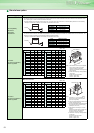
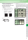
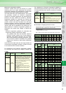
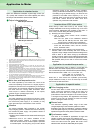
When the Mitsubishi standard squirrel-cage motor (SF-
JR, 4-pole) and inverter of the same capacity are used,
the torque characteristics are as shown below.
Output characteristics
*1 The 60Hz torque reference indicates that the rated torque of the motor running at
60Hz is 100%, and the 50Hz torque reference indicates that the rated torque of the
motor running at 50Hz is 100%
*2 Torque boost minimum (0%)
*3 Torque boost standard (initial value)
*4 Torque boost large (0.75K... 10%, 1.5K to 3.7K... 7%, 5.5K, 7.5K... 6%, 11K or more... 4%)
*5 Enabled for torque boost adjustment (3.7kW or less) or simple magnetic flux vector
control (slip compensation setting)
*6 A general-purpose, squirrel-cage motor must be used at lower continuous operating
torque in rated operation as shown in the chart since the cooling capability of the fan
installed on the rotor reduces at a lower speed. (Instantaneous torque occurs)
*7 200/220V 60Hz or 200V 50Hz in the chart indicates a motor torque standard (base
frequency set in Pr. 3 of the inverter) and is not the frequency of the power supply.
You can also set 60Hz in a 50Hz power supply area.
*8 As shown in the chart, the 60Hz torque reference setting allows you to use the motor
more efficiently as it can bring out the 100% torque of the motor continuously.
*9 This chart shows the characteristic available when a constant-torque load is selected
for load pattern selection (Pr. 14).
Motor loss and temperature rise
The motor operated by the inverter has a limit on the
continuous operating torque since it is slightly higher in
temperature rise than the one operated by a commercial
power supply. At a low speed, reduce the output torque of
the motor since the cooling effect decreases. When
100% torque is needed continuously at low speed,
consider using a constant-torque motor.
Torque characteristic
The motor operated by the inverter may be less in motor
torque (especially starting torque) than the one driven by
the commercial power supply. It is necessary to fully
check the load torque characteristic of the machine.
Vibration
The machine-installed motor operated by the inverter
may be slightly greater in vibration than the one driven by
the commercial power supply. The possible causes of
vibration are as follows.
1.Vibration due to imbalance of the rotator itself including the
machine
2.Resonance due to the natural oscillation of the
mechanical system. Caution is required especially
when the machine used at constant speed is operated
at variable speed. The frequency jump function allows
resonance points to be avoided during operation.
(During acceleration/deceleration, the frequency within
the setting range is passed through.) An effect is also
produced if the PWM carrier frequency in Pr. 72 is
changed. When a two-pole motor is operated at higher
than 60Hz, caution should be taken since such
operation may cause abnormal vibration.
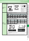
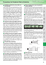
When driving a 400V class motor by the inverter, surge
voltages attributable to the wiring constants may occur at the
motor terminals, deteriorating the insulation of the motor. In
such a case, consider taking the following measures.
(1) Rectifying the motor insulation
1. Use a "400V class inverter driven insulation-
enhanced motor".
Note: The four poles of the Mitsubishi standard
motor (SF-JR, SB-JR) have the 400V class
inverter driving insulation-enhanced feature.
2. For the dedicated motor such as the constant-torque
motor and low-vibration motor, use the "inverter-
driven, dedicated motor".
(2) Suppressing the surge voltage on the inverter side
Connect a filter on the secondary side of the inverter to
suppress a surge voltage so that the terminal voltage of the
motor is 850V or less. When driving by the Mitsubishi
inverter, connect an optional surge voltage suppression filter
(FR-ASF-H) for the 55K or less and an optional sine wave
filter (MT-BSL, BSC) for the 75K or more on the inverter
output side.
Since a constant-torque motor is greater in current than the
standard motor, the inverter capacity may be one rank higher.
For a constant-torque motor, decrease the torque boost setting.
Recommended value 0.75kW... 6%, 1.5 to 3.7kW... 4%,
5.5 to 7.5kW...3%, 11 to 37kW...2%,
45 to 55kW...1.5%, 75k or more...1%
When two or more motors are operated synchronously,
torque imbalance is likely to occur as motor slip is smaller
than that of the standard motor.
Pole changing motor
As this motor differs in rated current from the standard
motor, confirm the maximum current of the motor and
select the inverter. Be sure to change the number of
poles after the motor has stopped. If the number of poles
is changed during rotation, the regenerative overvoltage
protecion circuit may be activated to cause an inverter
alarm, coasting the motor to a stop.
Geared motor
The continuous operating rotation range of this motor
changes depending on the lubrication system and maker.
Especially in the case of oil lubrication, continuous operation
in the low speed range only can cause gear seizure. For fast
operation at higher than 60Hz, please consult the maker.
Synchronous motor
This motor is not suitable for applications of large load
variation or impact, where out-of-sync is likely to occur.
Please contact us when using this motor because its starting
current and rated current are greater than those of the
standard motor and will not rotate stably at low speed.
Application to standard motor
60Hz torque reference
50Hz torque reference
0 1 3 6 20 30 60
120
200V
220V
*2*4*5 *3
Short time maximum torque*1
Output
frequency (Hz)
Continuous operation torque
(*6 to 8)
120
110
100
80
70
63
100
90
80
50
45
30
20
10
Continuous output torque (%)
Short time maximum torque (%)
0 1 3 6 20 30 50
120
*2*4*5 *3
Short time maximum torque*1
Continuous operation torque
(*6 to 8)
104
95
80
67
53
85
75
65
38
45
25 25
9
Continuous output torque (%)
Short time maximum torque (%)
Output
frequency (Hz)
Inverter-driven 400V class motor
Application to constant-torque motor
Application to special motors
Application to Motor