


Features
Standard
Specifications
Outline
Dimension
Drawings
Operation
Panel
Protective
Functions
OptionsInstructionsMotorCompatibilityWarrantyInquiry
Peripheral Devices
Why energy
savings?
Terminal Connection
Diagram
Terminal Specification
Explanation
Parameter
List
Explanations
of
Parameters
60
Installation and selection of moulded case
circuit breaker
Install a moulded case circuit breaker (MCCB) on the power
receiving side to protect the wiring of the inverter primary
side. For MCCB selection, refer to page 57 since it depends
on the inverter power supply side power factor (which
changes depending on the power supply voltage, output
frequency and load). Note that the operation characteristics
of the completely electromagnetic MCCB changes
according to the higher harmonic current, so a larger
capacity must be selected. (Check it in the data of the
corresponding breaker.) As an earth (ground) leakage
breaker, use the Mitsubishi earth (ground) leakage breaker
designed for harmonics and surges. (Refer to page 58.)
When installing a moulded case circuit breaker on the
secondary side of the inverter, contact each manufacturer
for selection of the moulded case circuit breaker.
Handling of primary side magnetic contactor
For operation via external terminal (terminal STF or STR
used), provide a primary side MC to prevent an accident
caused by a natural restart at power recovery after a power
failure, such as an instantaneous power failure, and to
ensure safety for maintenance work. Do not use this
magnetic contactor to make frequent starts and stops. (The
switching life of the inverter input circuit is about 1,000,000
times.) For parameter unit operation, an automatic restart
after power failure is not made and the MC cannot be used
to make a start. Note that the primary side MC can stop the
operation, but the regenerative brake specific to the inverter
does not operate and the motor coasts to stop.
Handling of secondary side magnetic contactor
Switch the magnetic contactor between the inverter and
motor only when both the inverter and motor are at a
stop. When the magnetic contactor is turned on while the
inverter is operating, overcurrent protection of the inverter
and such will activate. When an MC is provided to switch
to a commercial power supply, for example, it is
recommended to use commercial power supply-inverter
switchover operation Pr. 135 to 139.
Thermal relay installation
The inverter has an electronic thermal relay function to
protect the motor from overheating. However, when running
multiple motors with one inverter or operating a multi-pole
motor, provide a thermal relay (OCR) between the inverter
and motor. In this case, set the electronic thermal relay
function of the inverter to 0A. And for the setting of the
thermal relay, add the line-to-line leakage current (refer to
page 61) to the current value on the motor rating plate.
For low-speed operation where the cooling capability of
the motor reduces, it is recommended to use a thermal
protector or thermistor-incorporated motor.
Secondary side measuring instrument
When the wiring length between the inverter and motor is
long, select the device that has enough current rating.
Otherwise the measuring instrument or CT which is used
especially for the 400V class small-capacity inverter may
generate heat due to the influence of line leakage current.
To measure and display the output voltage and output
current of the inverter, it is recommended to use the
terminal AM-5 output function of the inverter.
Disuse of power factor improving capacitor
(power capacitor)
The power factor improving capacitor and surge suppressor
on the inverter output side may be overheated or damaged by
the harmonic components of the inverter output. Also, since
an excessive current flows in the inverter to activate
overcurrent protection, do not install a capacitor or surge
suppressor. For power factor improvement, use the power
factor improving DC reactor (see page 51).
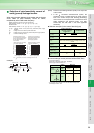
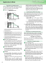
Wire thickness and wiring distance
When the wiring length between the inverter and motor is
long, use thick wires so that the voltage drop of the main
circuit cable is 2% or less especially at low frequency
output. (A selection example for the wiring distance of
20m is shown on page 57)
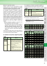
Especially at a long wiring distance, the maximum wiring
length should be within 500m since the overcurrent
protection function may be misactivated by the influence of a
charging current due to the stray capacitances of the wiring.
(The overall wiring length for connection of multiple motors
should be within the value in the table below.)
Use the recommended connection cable when installing
the operation panel away from the inverter unit or when
connecting the parameter unit.
For remote operation via analog signal, wire the control
cable between the operation box or operation signal and
inverter within 30m and away from the power circuits
(main circuit and relay sequence circuit) to prevent
induction from other devices.
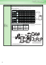
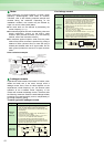
When using the external potentiometer instead of the
parameter unit to set the frequency, use a shielded or
twisted cable, and do not earth (ground) the shield, but
connect it to terminal 5 as shown below.
Earth (Ground)
When the inverter is run in the low acoustic noise mode,
more leakage currents occur than in the non-low acoustic
noise mode due to high-speed switching operation. Be
sure to use the inverter and motor after grounding
(earthing) them. In addition, always use the earth
(ground) terminal of the inverter to earth (ground) the
inverter. (Do not use the case and chassis)
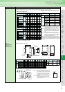
Pr. 72 PWM frequency
selection setting
(carrier frequency)
0.75K 1.5K 2.2K or more
2 300m 500m 500m
3 to 15 200m 300m 500m
Twisted cable
Frequency setting
potentiometer
(3)
(1)
(2)
10 (10E)
2
5
Shielded cable
(3)
(2)
(1)
10 (10E)
2
5
Frequency setting
potentiometer
Precautions for Peripheral Device Selection