


41
indicates simple mode parameters and indicates extended parameters. When setting parameters, refer to the instruction manual (applied) and understand instructions.
Pr.
Pr.
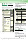
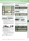
You can use the setting dial of the operation panel (FR-DU07)
like a potentiometer to perform operation.
The key operation of the operation panel can be disabled.
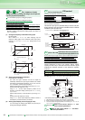
Use these parameters to select/change the input terminal functions.
*1 When Pr. 59 Remote function selection = "1" or "2", the functions of the RL,
RM and RH signals are changed as given in the table.
*2 The OH signal turns on when the relay contact "opens".
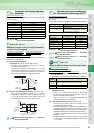
You can change the functions of the open collector output
terminal and relay output terminal.
* Setting can be made for the 75K or more.
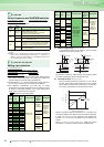
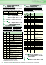
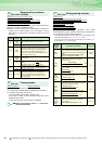
Operation selection of the
operation panel
Pr.161 Frequency setting/key lock operation selection
Pr.161 Setting Description
0 (initial value) Setting dial frequency setting mode
Key lock mode
invalid
1 Setting dial potentiometer mode
10 Setting dial frequency setting mode
Key lock mode
valid
11 Setting dial potentiometer mode
162 to 165
Refer to the section about Pr. 57 and
other relevant parameters.
166, 167
Refer to the section about Pr. 150 and
other relevant parameters.
168, 169
Parameter for manufacturer setting. Do not set.
170, 171
Refer to the section about Pr. 52 and
other relevant parameters.
172 to 174
Refer to the section about Pr. 160 and
other relevant parameters.
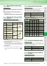
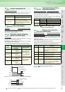
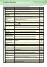
Function assignment of
input terminal
Pr.178 STF terminal function selection Pr.179 STR terminal function selection
Pr.180 RL terminal function selection Pr.181 RM terminal function selection
Pr.182 RH terminal function selection Pr.183 RT terminal function selection
Pr.184 AU terminal function selection Pr.185 JOG terminal function selection
Pr.186 CS terminal function selection Pr.187 MRS terminal function selection
Pr.188
STOP terminal function selection
Pr.189 RES terminal function selection
Pr.178 to
Pr.189
Setting
Signal
Name
Function
0 RL
Pr.59 =0
(initial value)
Low speed operation command
Pr.59 =1, 2 *1 Remote setting (setting clear)
1 RM
Pr.59 =0
(initial value)
Middle speed operation
command
Pr.59 =1, 2 *1 Remote setting (deceleration)
2 RH
Pr.59 =0
(initial value)
High speed operation command
Pr.59 =1, 2 *1 Remote setting (acceleration)
3 RT Second function selection
4 AU Terminal 4 input selection
5 JOG Jog operation selection
6 CS
Selection of automatic restart after instantaneous
power failure, flying start
7 OH External thermal relay input *2
8 REX
15 speed selection
(combination with three speeds RL, RM, RH)
10 X10
Inverter operation enable signal
(FR-HC, FR-CV connection)
11 X11
FR-HC connection, instantaneous power failure
detection
12 X12 PU operation external interlock
14 X14 PID control valid terminal
16 X16 PU-external operation switchover
24 MRS Output stop
25 STOP Start self-holding selection
60 STF
Forward rotation command
(assigned to STF terminal (Pr. 178) only)
61 STR
Reverse rotation command
(assigned to STR terminal (Pr. 179) only)
62 RES Inverter reset
63 PTC
PTC thermistor input
(assigned to AU terminal (Pr. 184) only)
64 X64 PID forward/reverse action switchover
65 X65 NET/PU operation switchover
66 X66 External/NET operation switchover
67 X67 Command source switchover
9999 No function
Pr.
161
Pr.
Pr.
Pr.
Pr.
Pr.
Pr.
178 to 18
9
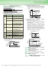
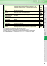
Terminal assignment of
output terminal
Pr.190 RUN terminal function selection Pr.191 SU terminal function selection
Pr.192 IPF terminal function selection Pr.193 OL terminal function selection
Pr.194 FU terminal function selection Pr.195
ABC1 terminal function selection
Pr.196
ABC2 terminal function selection
Pr.190 to Pr.196
Setting
Signal
Name
Function
Positive
logic
Negative
logic
0 100 RUN Inverter running
1 101 SU Up to frequency
2 102 IPF
Instantaneous power failure/
undervoltage
3 103 OL Overload alarm
4 104 FU Output frequency detection
5 105 FU2
Second output frequency
detection
5 105 FU2
Second output frequency
detection
7 107 RBP Regenerative brake prealarm *
10 110 PU PU operation mode
11 111 RY Inverter operation ready
12 112 Y12 Output current detection
13 113 Y13 Zero current detection
14 114 FDN PID lower limit
15 115 FUP PID upper limit
16 116 RL
PID forward/reverse rotation
output
17 MC1
Commercial power-supply
switchover MC1
18 MC2
Commercial power-supply
switchover MC2
19 MC3
Commercial power-supply
switchover MC3
25 125 FAN Fan fault output
26 126 FIN Heatsink overheat pre-alarm
45 145 RUN3
During inverter running and start
command is on
46 146 Y46
During deceleration at
occurrence of power failure
(retained until release)
47 147 PID During PID control activated
64 164 Y64 During retry
70 170 SLEEP During PID output suspension
90 190 Y90 Life alarm
91 191 Y91 Alarm output 3 (power-off signal)
92 192 Y92
Energy saving average value
updated timing
93 193 Y93 Current average monitor signal
94 194 ALM2 Alarm output 2
95 195 Y95 Maintenance timer signal
96 196 REM Remote output
98 198 LF Minor fault output
99 199 ALM Alarm output
9999 No function
232 to 239
Refer to the section about Pr.4 to Pr.6
240
Refer to the section about Pr. 72 and other
relevant parameters.
241
Refer to the section about Pr. 125, Pr.126
242, 243
Refer to the section about Pr. 73 and
other relevant parameters.
Pr.
190 to 19
6
Pr.
Pr.
Pr.
Pr.